Submerged arc welding: how it works – and why it deposits so much
Contents
Why SAW is used for long welds
On a vessel shell, the weld runs once around the entire circumference. On a heavy girder, it extends over several metres. When a lot of weld metal has to be deposited, a process that can work long and evenly pays off.
Submerged arc welding – UP in German, SAW internationally – does exactly that. As with MAG, an arc burns between wire and workpiece. Here, the weld pool is protected by flux, the shielding gases it releases and slag. From the outside, the arc stays hidden.
The basic form works with a solid wire electrode and carries process number 121 under DIN EN ISO 4063. This number appears in welding procedure specifications and procedure qualifications; the SAW process group as a whole is number 12.
Sequence: flux, wire, arc and slag
- Wire feed: the reel supplies the welding wire. Its path to the weld can be followed in red.
- Feed and contact tube: the rolls drive the wire; the contact tube transfers the welding current.
- Flux feed: the hopper deposits granular welding flux into the groove ahead of the weld.
- Flux recovery: behind the contact tube, a nozzle extracts the unfused flux. It is reused.
- Arc: it burns between the wire tip and the pool. Here it is visible through the cut; in operation it is covered by flux.
- Solidified weld: solid weld metal fills the V-groove between the two plates, visible in cross-section at the end face. On the right, ahead of the head, the groove is still open.
- Slag: fused flux solidifies behind the pool into a crust over the weld. It is removed once it has cooled.
- Weld pool: red marks the molten weld metal from wire and base metal. The horizontal arrow shows the head's travel.
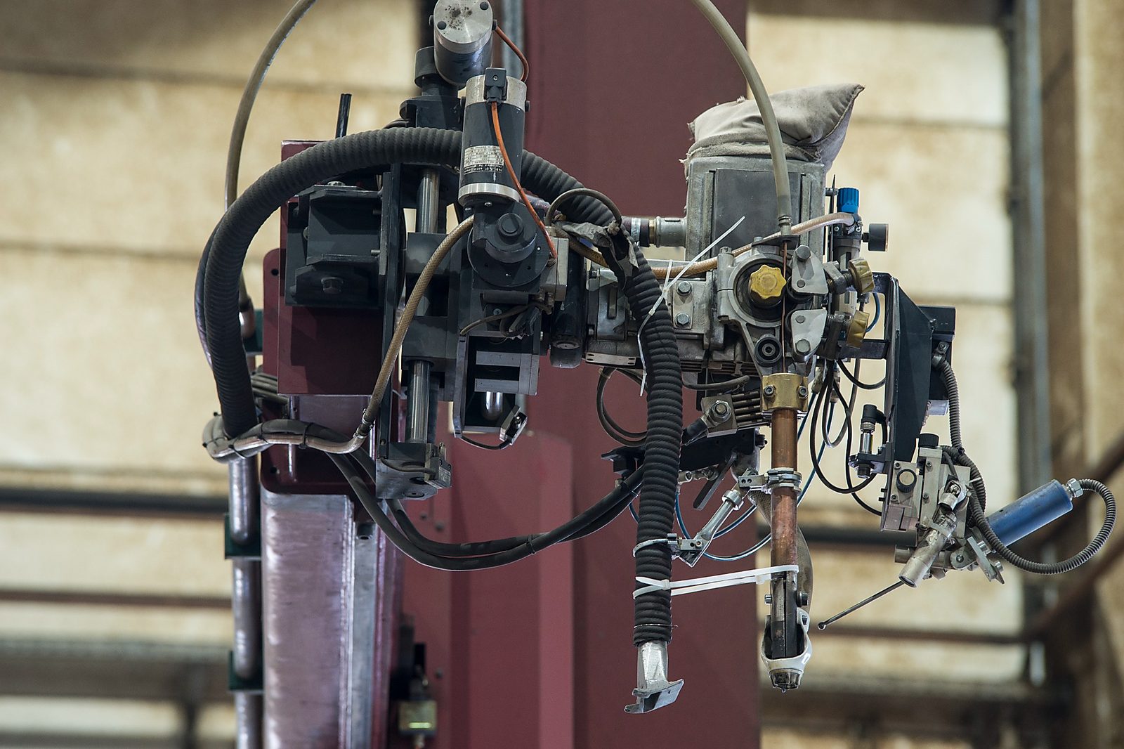
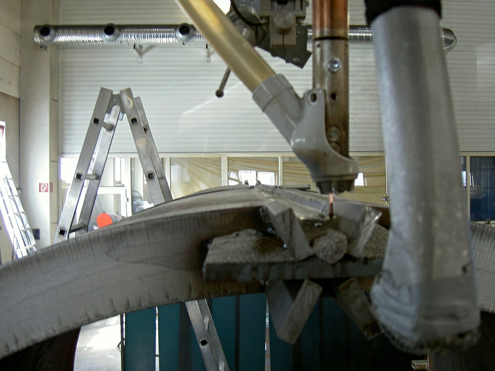
A SAW welding head performs several tasks at once while it travels along the weld at constant speed:
- Depositing flux: ahead of the arc, granular welding flux flows from a container on the welding head into the groove. The layer is deep enough to cover the arc completely.
- Feeding wire: the wire electrode runs continuously from the reel through a contact tube that transfers the welding current. The arc burns between the wire tip and the workpiece, in the middle of the flux.
- Weld pool and slag: wire and base metal melt to form the weld metal. Part of the flux melts with them and forms slag. It shields the molten metal from the air, shapes the weld surface and slows down cooling.
- Recovering flux: the unfused flux is extracted behind the welding head and reused.
- Removing slag: after cooling, the slag lies on the weld as a crust. It is removed completely before every further pass; otherwise slag inclusions remain in the weld.
Because the arc burns inside the flux, there is hardly any spatter, and arc glare and welding fume are much lower than with an open arc. The flip side: nobody sees the weld pool. Groove, welding head and travel path therefore have to be set up precisely before the start, and the weld position is guided mechanically during travel.
How much weld metal can be deposited per hour
For single-wire SAW, the welding institute TWI states a deposition rate of 3 to 16 kg/h. This refers to one hour of arc time. The values depend on the operating point and overlap with the ranges of other processes.
| Process | Deposition rate, indicative value |
|---|---|
| Manual metal arc welding with covered electrode | 0.4 to 5.5 kg/h |
| MAG welding | 0.6 to 12 kg/h |
| Flux-cored arc welding | 1 to 15 kg/h |
| Single-wire submerged arc welding | 3 to 16 kg/h |
The table shows TWI indicative values, not a performance commitment by Bock. Total production time also includes setting up, tacking, turning, slag removal and inspection. Only taken together do they show whether SAW saves time on a specific weld.
How flux, current and wire feed work together
The output comes from several conditions working together:
- High current melts a lot of wire: TWI gives 200 to 1,000 A for a single SAW wire, depending on its diameter. On thick plate, a 4 mm wire often runs at 600 to 900 A. The amount of wire melted rises with the current. The permissible values are set by the welding procedure specification.
- The flux keeps the heat in the process: it covers the arc, limits heat losses and allows a spatter-free welding process. This supports the high deposition rate. At the same time, shielding gases and slag form and shield the hot metal from its surroundings.
- Continuous feed keeps the process going: the wire is drawn from the reel while the head travels along the groove. Unlike manual welding with covered electrodes, there is no regular stop to change electrodes. On circumferential welds, the turning device provides the steady travel of the workpiece.
On a long weld, the process can spend much of its time with the arc burning. On a short weld, setting up takes a larger share. That is why the process is chosen for the whole task, including preparation and inspection.
The flux protects the weld – and helps determine its properties
The flux protects the weld pool and at the same time influences the weld metal. It can add or bind constituents and thereby change strength and toughness, among other things. Wire and flux are therefore selected as a matched combination.
DIN EN ISO 14171 classifies such wire-flux combinations for non-alloy and fine-grain steels. DIN EN ISO 14174 sets out the classification of fluxes. Which combination is used is stated in the welding procedure specification and backed by the procedure qualification.
By manufacturing method, a distinction is made between fused and agglomerated fluxes, among others. The former are produced from a melt, the latter by binding powdered raw materials into grains with a binder. The chemical composition is chosen to suit the material and the required weld metal properties.
Storage is part of the preparation as well. Damp flux can introduce hydrogen into the weld metal and so increase the risk of cold cracking. It is stored dry and, where the manufacturer specifies, re-dried.
Longitudinal or circumferential weld: what moves during welding
- Longitudinal weld: the complete SAW head with wire reel, feed, contact tube, flux hopper and flux recovery travels along the groove. The red arrow shows its travel.
- The workpiece stays still. Under the head, granular welding flux covers the weld; behind it lies the weld track.
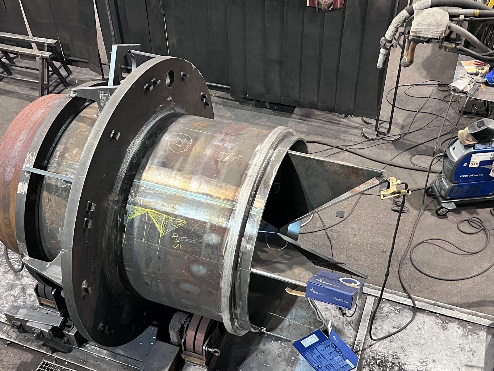
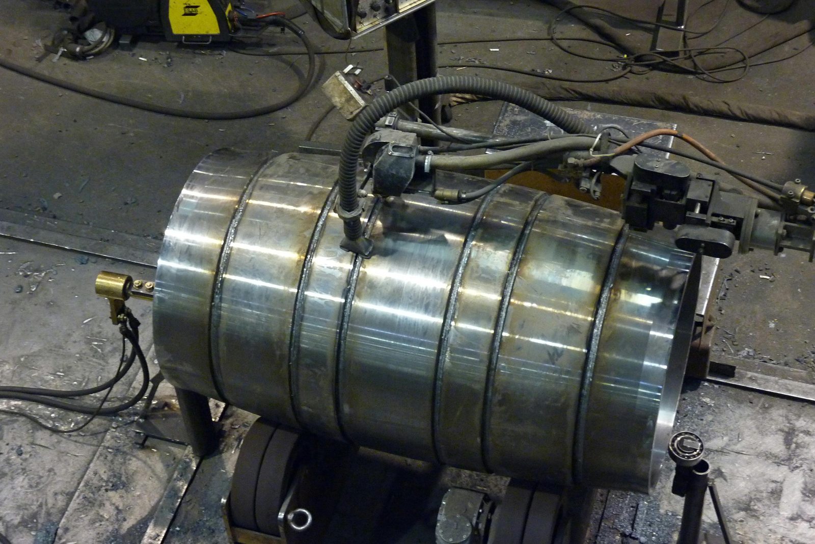
- Circumferential weld: the same SAW head sits on the fixed boom. Here too, flux flows ahead of the covered weld.
- Rolls turn the pipe under the head. The red line running round marks the circumferential weld; the curved arrow shows an example direction of rotation.
On a longitudinal weld, the welding head travels along the stationary workpiece. On a circumferential weld, by contrast, the head stays in place while rolls turn the workpiece beneath it. The rotational speed then determines the travel along the weld.
On a curved surface, weld pool and slag must stay on the weld until they solidify. To achieve this, the wire position relative to the top of the pipe is set to suit the diameter. Internal circumferential welds can be reached with the boom if pipe diameter and reach leave enough room.
For this, Bock has six turning roll sets for Ø 150 to 7,500 mm and components up to 60 t. Welding positioners up to 2,000 kg can tilt smaller assemblies and bring the weld into a suitable position.
Variants: single wire, cored wire, multiple wires, strip
The basic form works with a solid wire. There are also variants that raise the deposition rate further or serve a different purpose:
- One solid wire electrode (process 121): the basic form and the most common SAW process in steel construction. The joint preparation standard, DIN EN ISO 9692-2, also refers to it.
- Cored wire electrode (process 125): a tubular wire carries a filling inside that additionally alloys the weld metal or increases the deposition rate.
- Multiple wires: two or more wires melt in a common weld pool or in short succession. This produces more weld metal per metre of travel, for example on very long, thick longitudinal welds.
- Strip electrode: instead of a wire, a wide metal strip melts off. This variant is used mainly for surface cladding, for example to apply a wear-resistant or corrosion-resistant layer.
The further variants are not automatically suitable for every weld. Welding position and accessibility still have to be considered, as does the required deposition rate.
SAW, MAG and TIG compared
The processes have different strengths. Weld length, position, plate thickness and accessibility point the way:
| Process | Weld pool protection | Strong for | Limit |
|---|---|---|---|
| Submerged arc welding (121) | Flux and slag, arc covered | Long, straight longitudinal and circumferential welds in thick plate, large weld volumes, fully mechanised with consistent weld quality | Flat and horizontal positions only, set-up effort, slag removal after every pass, welding head needs an accessible, guided path |
| MAG welding (135) | Active shielding gas, open arc | Short and intermittent welds, complex assemblies, out-of-position welding, root passes and tack welds; manual to fully mechanised | Considerably less weld metal per hour than SAW on long welds in thick sections; spatter and welding fume |
| TIG welding (141) | Inert gas, non-consumable tungsten electrode, filler fed separately | Thin sheet, stainless steels, root passes, visible welds with high surface requirements | Low deposition rate, slow on thick sections |
Long, accessible welds on thicker plate are typical SAW tasks. For short connections and changing positions, MAG is often used. TIG offers finely controlled weld guidance, including on thin sheet. On one assembly, the processes can complement each other.
When submerged arc welding is not the right process
The high deposition rate is of little use if the head cannot reach the weld, the heat input becomes too high or setting up takes longer than welding. These cases limit its use:
- Out-of-position welding: flux and molten slag only stay on a horizontal surface. The joint preparation standard therefore covers only the flat position PA and the horizontal fillet weld PB to DIN EN ISO 6947. The horizontal position PC requires special preparation. Vertical-up and overhead welding are not done under flux.
- Short or intermittent welds: positioning the welding head, filling with flux, setting the travel path and tacking on run-off tabs takes time. This only pays off above a certain weld length. Many short connection welds are finished faster with MAG.
- Hard-to-reach welds: the welding head with flux feed needs room and a guided path. It cannot reach welds in tight corners or inside small cross-sections.
- Thin sheet: high welding current and deep penetration take thin sheet to the limit of burn-through. Here, MAG or TIG is the safe choice.
- Demanding heat control: SAW puts a lot of heat into the component. For quenched and tempered fine-grain structural steels, the welding procedure specification therefore limits the heat input, because too much heat reduces toughness next to the weld. SAW is still possible there, but with tighter parameters and often more passes.
If an assembly can be turned appropriately, other welds also become accessible for SAW. Short connections or a root pass can still be welded with MAG. This way, the processes can be combined on the same part.
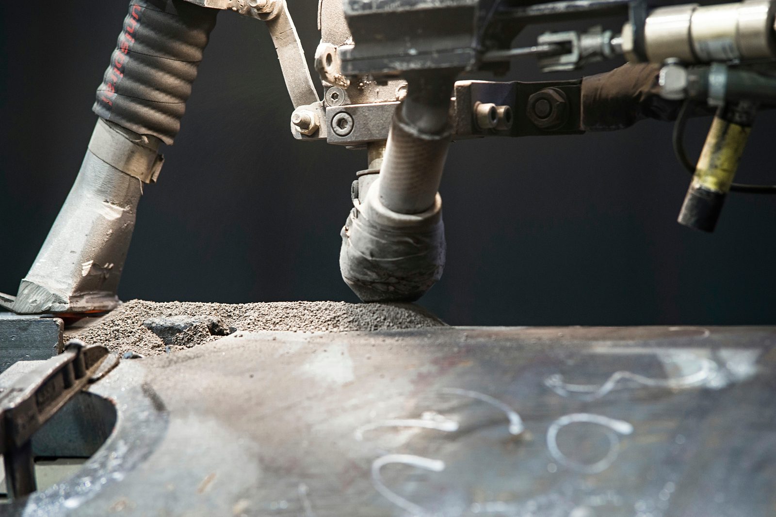
Submerged arc welding at Bock: equipment, materials, certification
Joint preparation and root: what matters in SAW
- The cap completes the weld at the top surface.
- Fill layers build up the cross-section; slag is removed before the next layer.
- The root has to be made reliably with a suitable welding sequence.
- Backing is shown dashed as one possible option. A MAG root run or welding from the reverse side are other solutions and are not drawn at the same time.
The joint preparation is matched to the penetration of the SAW process. DIN EN ISO 9692-2 describes groove shapes for submerged arc welding of steel with one wire electrode: for full-penetration welds in positions PA and PB. For partial-penetration welds, other shapes can apply if the application standard or an agreement provides for them.
At the root, the molten weld metal has to be held in place. This can be done with backing on the reverse side, by first welding a MAG root, or by a sealing run from the second side. The choice depends on plate thickness, accessibility and inspection requirements.
On longitudinal welds, run-on and run-off tabs are often tacked on. This places the weld start and end crater outside the actual component.
An even groove helps the mechanically guided welding head to follow the weld reliably. At Bock, bevels are therefore machine-made: by flame cutting up to ±45° or on the edge milling machine up to 12 × 45°. Bevel cutting is explained in the article How does flame cutting work?
What is needed to plan the weld
The drawing describes the required joint: weld type and throat thickness or full penetration, material, quality level to DIN EN ISO 5817, where applicable the execution class to DIN EN 1090-2, and the extent of inspection.
On this basis, the welding shop plans the execution. For example, MAG may be planned for a root pass and SAW for the fill passes. A binding process requirement is taken into account; without one, production can choose the suitable combination.
Information on later loading, subsequent machining and end-customer requirements is helpful too. Such details should be available early so that welding sequence, inspection and further processing fit together.
Typical components with SAW welds
How to recognise a component for submerged arc welding: it has long, continuous welds that lie horizontally or can be turned into that position. Typical examples are:
- Pipes and pipe sections from rolled plate: each section gets a longitudinal weld. When several sections are joined into a long pipe, circumferential welds are added.
- Vessels and cylindrical shells: longitudinal welds on the shell and circumferential welds to heads, flanges and adjacent sections, welded on turning rolls.
- Box girders and plate girders: the web-to-flange welds run along the entire girder length, as fillet welds in horizontal position PB or, with the girder tilted, in flat position PA.
- Heavy welded structures from thick plate: large butt welds whose root is laid with MAG and whose fill and cap passes are welded under flux.
Whether these geometries are actually welded with SAW also depends on accessibility and positioning. Short connection welds on the same assembly may, for example, be made with MAG.
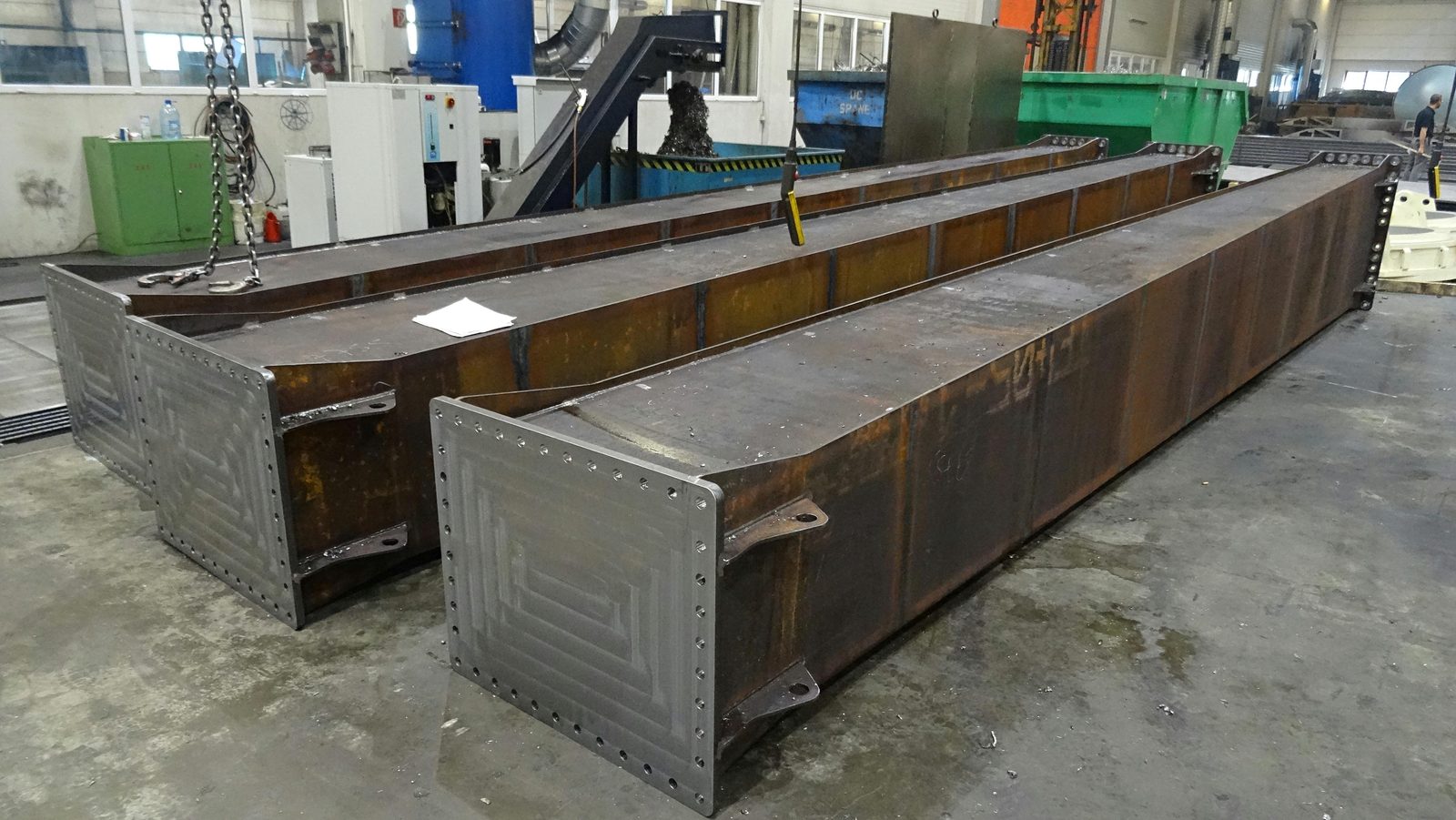
From drawing to inspected weld: how a SAW weld is made at Bock
Between enquiry and finished weld there are seven steps. Welding under flux is only one of them:
- Reading the drawing: weld type, throat thickness, material, quality level and execution class determine which welds are made under flux and which with MAG. The assignment is the responsibility of our welding supervision with IWE and EWE qualifications.
- Setting the welding procedure specification: wire-flux combination, pass sequence, current, voltage and speed are set out in the welding procedure specification, backed by the procedure qualification. Processes 121 (SAW) and 135 (MAG) are both within the scope of our welding shop certification to EN ISO 3834-2, for execution class EXC3 to DIN EN 1090-2.
- Preparing and tacking the groove: bevel by flame cutting or on the edge milling machine, clean the groove faces, tack the parts, attach run-on and run-off tabs.
- Laying the root: with MAG or on backing, depending on plate thickness and accessibility of the reverse side.
- Positioning and welding: the component goes onto turning rolls or a positioner, and the head is aligned with the groove. Then the SAW passes follow; after every pass, the slag is removed completely.
- Inspecting: visual testing, penetrant testing and magnetic particle testing are carried out in-house with Level 2 qualification to DIN EN ISO 9712, ultrasonic and radiographic testing by qualified partners. The benchmark is the quality level from the drawing.
- Further processing: where the component is machined afterwards, vibration stress relief can reduce the residual stress from welding beforehand. CNC machining, blasting and painting follow in the same plant.
Subsequent machining is already taken into account when planning the weld. Where milling or drilling is to follow welding, the necessary machining allowance is left in place. External testing partners are brought in for the methods assigned to them.
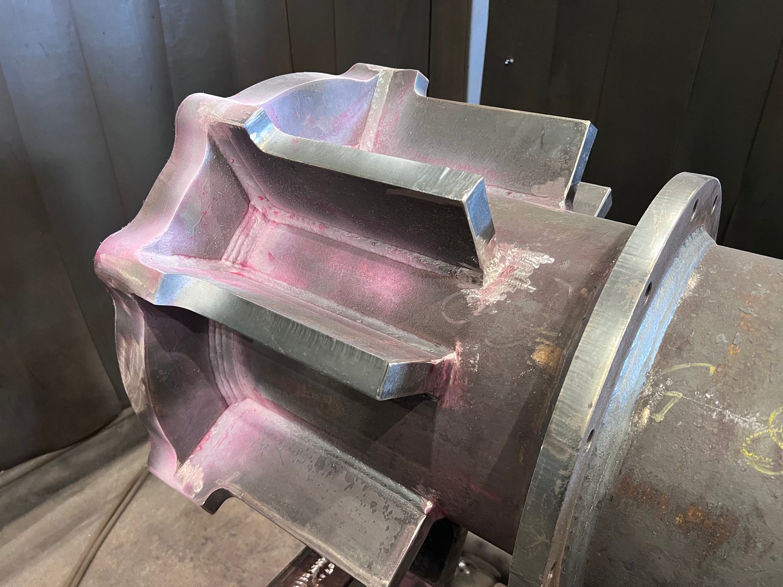
Hidden weld pool: why the operator remains decisive
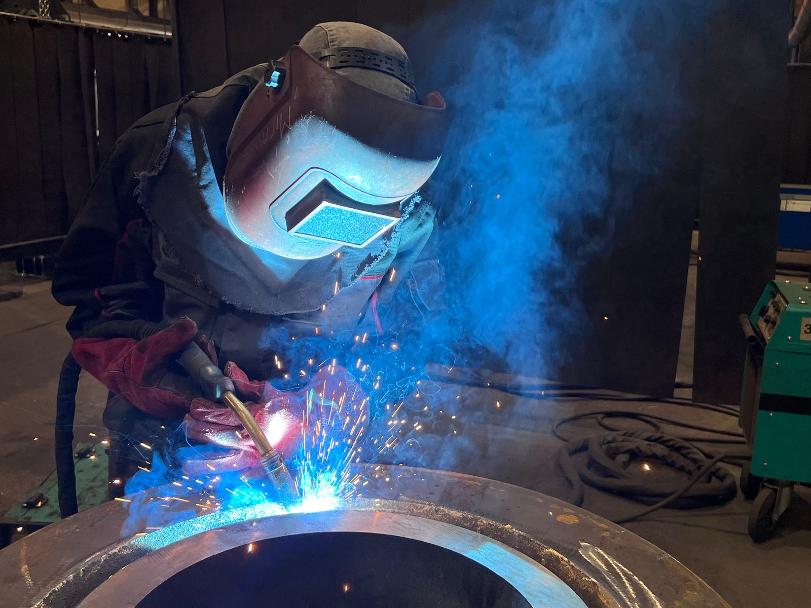
Before the equipment starts, the operator aligns the head with the groove and sets wire feed, current, voltage and travel speed according to the welding procedure specification. During travel, they monitor seam tracking and welding data and correct as needed. Between passes, the slag is removed and the weld is checked.
This calls for a different qualification than manual welding: DIN EN ISO 9606-1 tests the welder, DIN EN ISO 14732 the operator of a mechanised installation if they control the welding parameters. Its focus is on setting up and process control.
At Bock, both sides belong to one position. The vacancy Welder (m/f/d) for MAG, TIG and submerged arc covers manual welding on assemblies as well as working at the SAW columns.
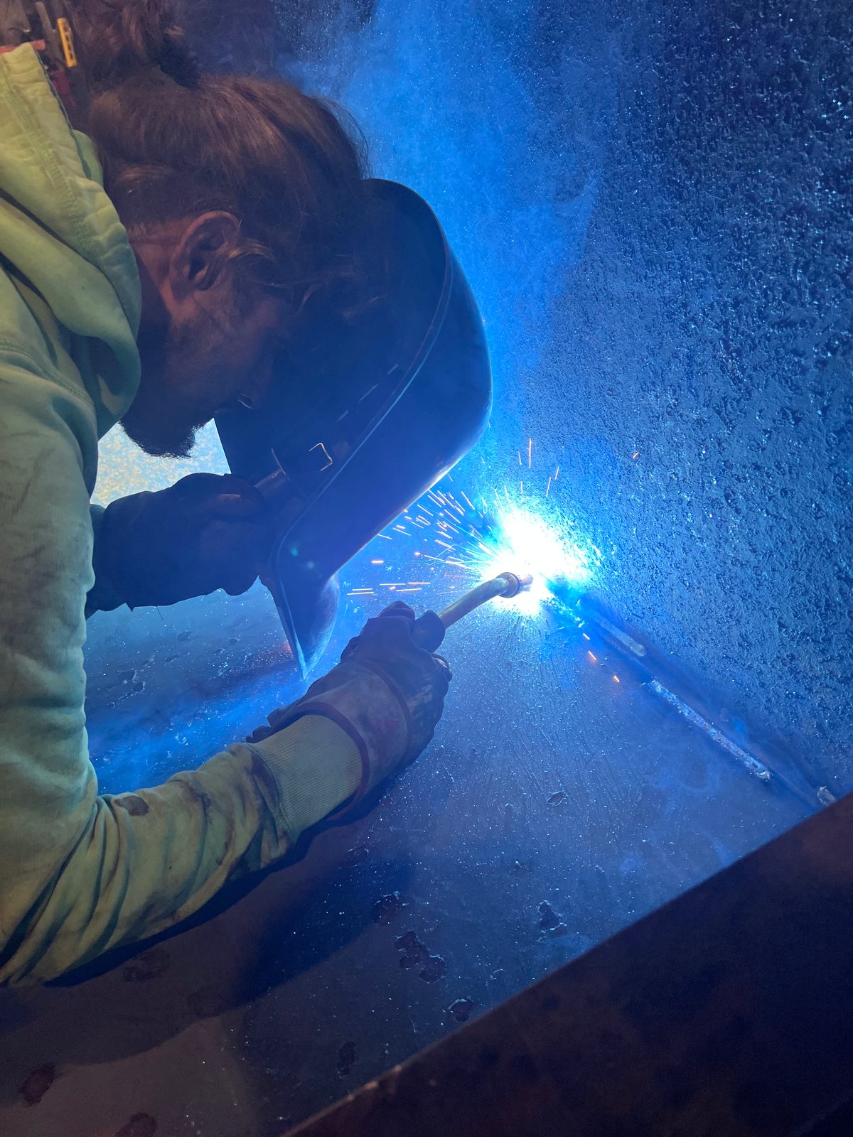
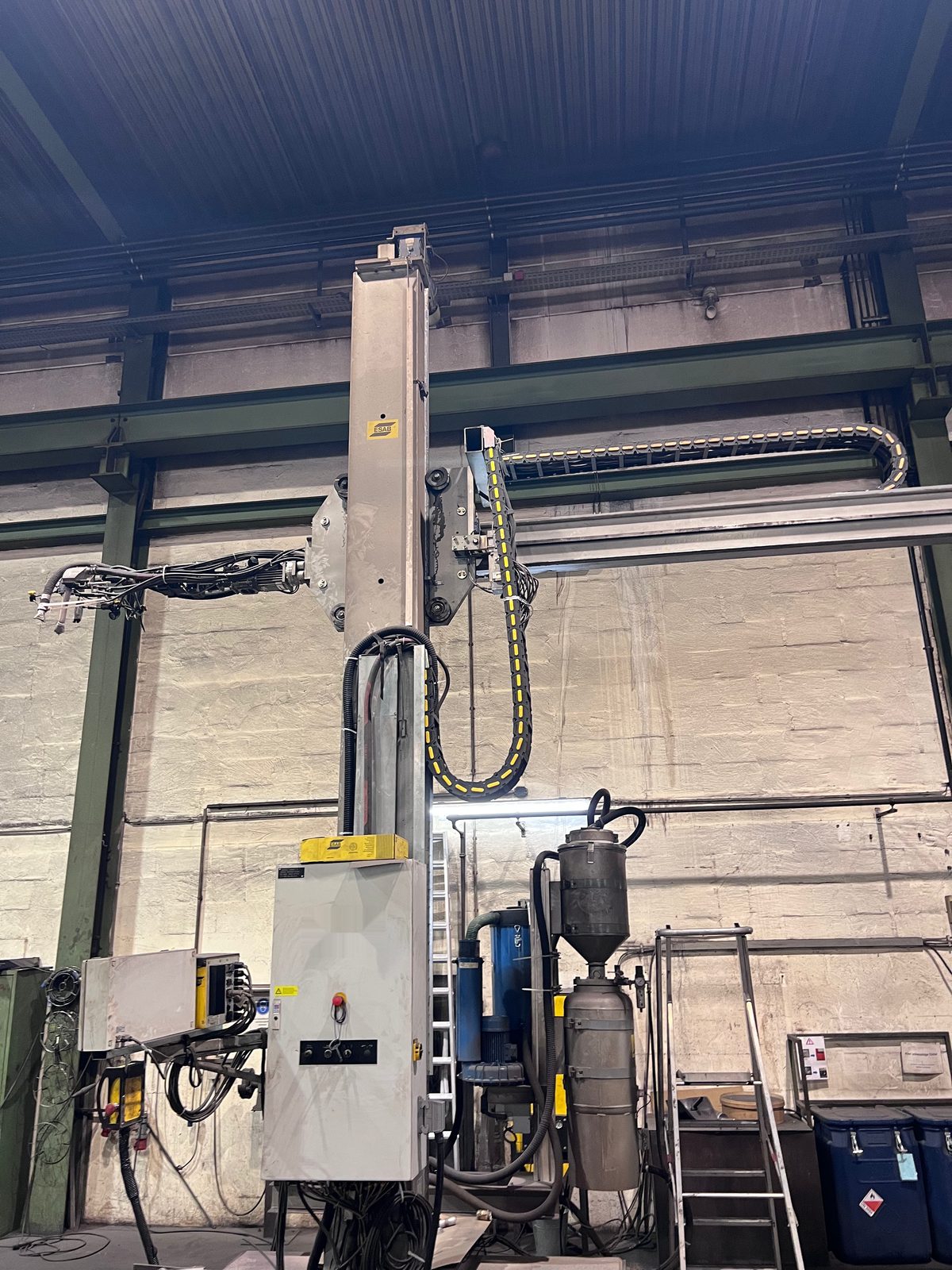
The equipment: three SAW columns in Lorch
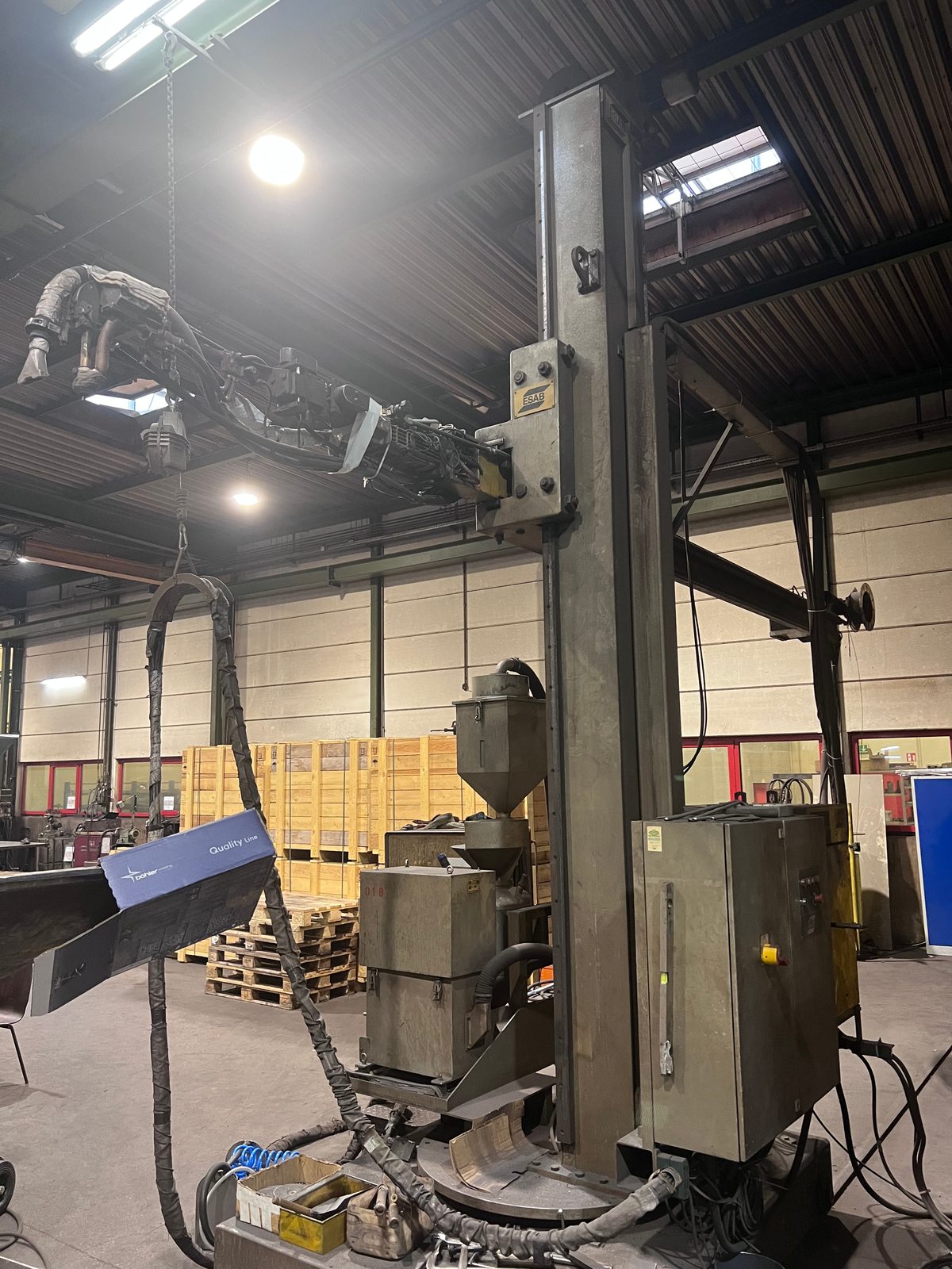
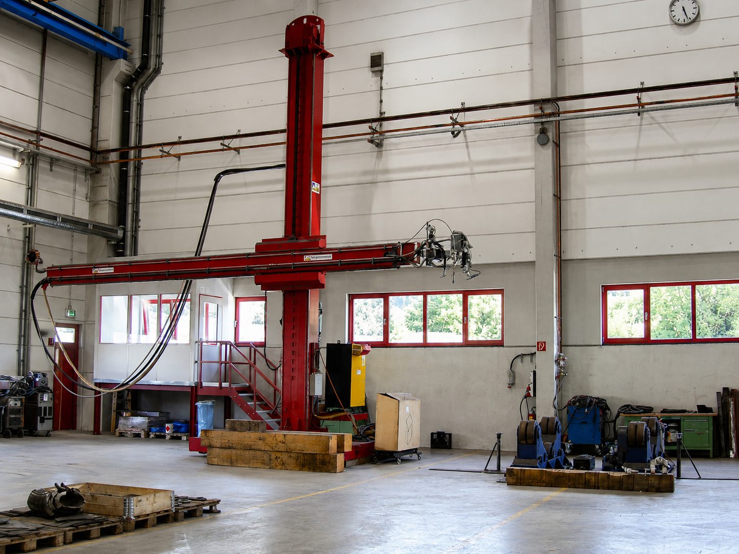
Our production in Lorch has three ESAB SAW column-and-boom units. All three process wire up to 4 mm in diameter:
- ESAB ROMAR RM7070 SAR 400 with 7 m reach, 7 m working height and up to 1,250 A welding current
- ESAB MKP with 5 m reach, 5 m working height and 800 A
- ESAB CAB 300M with 4 m reach, 5 m working height and 800 A
Reach and working height determine how far from the column and how high above the workshop floor the head can reach a weld – and so also how deep it can travel into a pipe. The three columns work together with the turning rolls; heavy parts up to 50 t are moved by the workshop's crane system.
From the workshop: components and equipment
The photos show pipe sections, large pipes and welded structures at the SAW equipment in our production. They show how much room the welding head and workpiece need.
Submerged arc welding in pictures
The photos from our production lead to the relevant sections.
-
The SAW equipment -
2 Sequence: flux, wire, arc and slag -
2 Sequence: flux, wire, arc and slag -
6 Longitudinal or circumferential weld: what moves during welding -
6 Longitudinal or circumferential weld: what moves during welding -
9 When submerged arc welding is not the right process -
12 Typical components with SAW welds -
14 Hidden weld pool: why the operator remains decisive -
15 The equipment: three SAW columns in Lorch
Frequently asked questions about submerged arc welding
How does submerged arc welding work?
A wire electrode is fed continuously, and the arc burns between wire and workpiece under a layer of granular welding flux. Part of the flux melts into slag, protects the weld pool and shapes the weld. The remaining flux is extracted and reused. The welding head travels along the weld fully mechanised, or the workpiece turns beneath it. This produces long longitudinal and circumferential welds with a high deposition rate and deep penetration.
What does the abbreviation SAW stand for in welding?
SAW stands for submerged arc welding – the arc burns submerged under a layer of flux. In German the process is called Unterpulverschweißen, abbreviated UP. In the list of welding processes to DIN EN ISO 4063 it forms group 12; the basic form with one solid wire electrode has reference number 121.
What does the flux do in submerged arc welding?
The flux covers the arc and partly melts into slag. The slag shields the molten metal from the air, shapes the weld surface and slows down cooling. The flux also influences the chemical composition of the weld metal. That is why wire and flux are chosen as a combination and classified to DIN EN ISO 14171.
In which welding positions can submerged arc welding be used?
In practice only horizontally: in flat position PA and as a horizontal fillet weld PB to DIN EN ISO 6947. In other positions, flux and molten slag would slide off. The horizontal position PC is only possible with special preparation, vertical-up and overhead not at all. That is why pipes and vessels are turned in turning devices so that the weld lies on top.
SAW or MAG – which process suits my weld?
Long, straight longitudinal and circumferential welds in thick plate in a horizontal position are a case for SAW: more weld metal per hour and a consistent weld over the entire length. Short or intermittent welds, complex assemblies and out-of-position welds are a case for MAG. The two are often combined, for example with a MAG root and SAW fill and cap passes. We make the assignment based on your drawing.
Do I have to state on the drawing that the weld is made under flux?
No. The drawing specifies the result: weld type, throat thickness or full penetration, material, quality level to DIN EN ISO 5817 and, in steel construction, the execution class. Which process makes which weld is set out in our welding procedure specifications. Prescribing a process is only necessary if an end-customer requirement calls for it.
Will my component distort during submerged arc welding?
Every weld introduces heat and leaves residual stress, under flux too. SAW puts a lot of heat in per pass but needs fewer passes for the same weld than a manual process. A symmetrical welding sequence, tacking and fixtures help against distortion. If the component is machined afterwards, the remaining residual stress can be reduced beforehand by vibration stress relief so that it does not distort later during machining.
Which SAW equipment does Bock use?
Three ESAB SAW column-and-boom units: the ESAB ROMAR RM7070 SAR 400 with 7 m reach and up to 1,250 A, the ESAB MKP with 5 m and the ESAB CAB 300M with 4 m reach, both at 800 A. All three process wire up to 4 mm in diameter. Pipes and vessels turn on six turning roll sets for Ø 150 to 7,500 mm and up to 60 t; heavy parts up to 50 t are moved by the crane system.
Sources and standards
The indicative deposition rates come from freely available technical articles by the British welding institute TWI. Standards are named with their number and edition; their text is paid for and therefore not linked.
- Indicative deposition rates for manual metal arc, MAG, flux-cored and single-wire submerged arc welding Job Knowledge 97 – Welding costs, continued (Table 1: Indicative deposition rates)
- Welding current per wire (200 to 1,000 A, 600 to 900 A on thick plate), continuous wire feed and mechanised guidance Job Knowledge 16 – Equipment for submerged arc welding
- Freedom from spatter and low heat loss under the flux layer Job Knowledge 5 – Submerged arc welding process
- Group 12 and reference numbers 121 and 125 of submerged arc welding, 135 (MAG) and 141 (TIG) DIN EN ISO 4063 – Welding, brazing, soldering and cutting – Nomenclature of processes and reference numbers
- Classification of wire-flux combinations for non-alloy and fine-grain steels DIN EN ISO 14171 – Welding consumables – Solid wire electrodes, tubular cored electrodes and electrode/flux combinations for submerged arc welding of non-alloy and fine grain steels – Classification
- Classification of welding fluxes DIN EN ISO 14174 – Welding consumables – Fluxes for submerged arc welding and electroslag welding – Classification
- Groove shapes for submerged arc welding with one wire electrode, full-penetration welds, positions PA and PB DIN EN ISO 9692-2 – Welding and allied processes – Joint preparation – Part 2: Submerged arc welding of steels
- Designation of welding positions PA, PB and PC DIN EN ISO 6947 – Welding and allied processes – Welding positions
- Quality levels as a drawing requirement DIN EN ISO 5817 – Quality levels for imperfections in fusion-welded joints
- Qualification testing of operators of fully mechanised welding equipment who control the welding parameters DIN EN ISO 14732 – Welding personnel – Qualification testing of welding operators and weld setters for mechanized and automatic welding of metallic materials
- Welder qualification test for manual welding DIN EN ISO 9606-1 – Qualification testing of welders – Fusion welding – Part 1: Steels
- Scope of the welding shop certification with processes 121 and 135 DIN EN ISO 3834-2 – Quality requirements for fusion welding of metallic materials – Part 2: Comprehensive quality requirements
- Execution class EXC3 as a drawing requirement in steel construction DIN EN 1090-2 – Technical requirements for the execution of steel structures
- Level 2 qualification of testing personnel for visual, penetrant and magnetic particle testing DIN EN ISO 9712 – Qualification and certification of NDT personnel