How does flame cutting work? Oxy-fuel cutting from 25 to 200 mm
Contents
What is flame cutting – and how does it work?
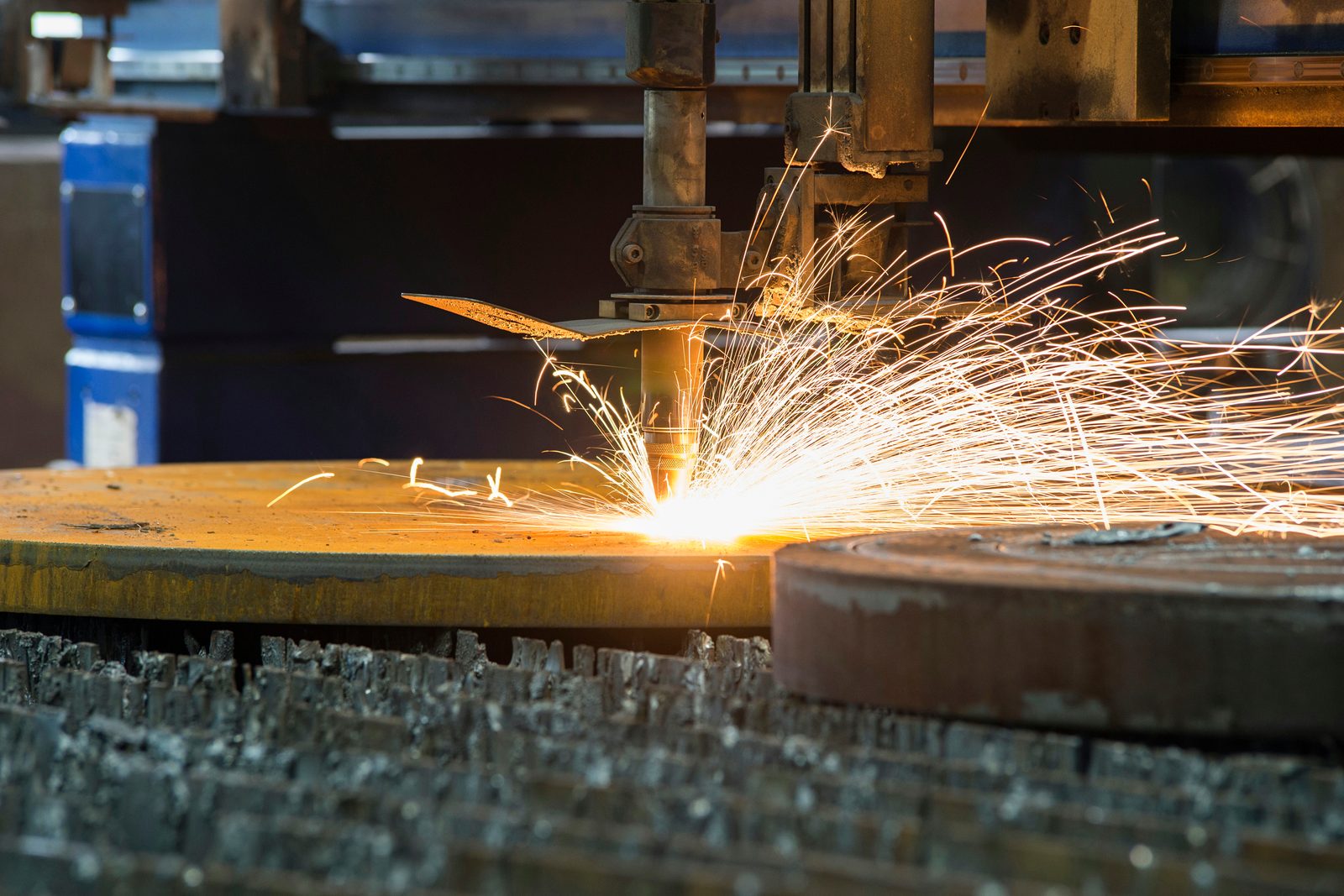
Flame cutting – more precisely, oxy-fuel flame cutting – is a thermal cutting process for unalloyed and low-alloy steel. A fuel gas–oxygen flame heats the cutting point to an ignition temperature of around 1,150 °C. The torch then opens the cutting oxygen: the jet burns the iron into liquid slag and blows it downwards out of the kerf.
The decisive difference from laser or plasma cutting: the material is not melted but burnt. The combustion of the iron itself supplies a large part of the heat required. This is why the energy demand rises only moderately with material thickness – and that is exactly where the process draws its strength on thick cross-sections.
The prerequisite is a material whose ignition temperature lies below its melting point and whose oxides run off as a liquid. This applies to structural steel and many fine-grain structural steels – but not to stainless steel or aluminium. Carbon also sets a limit: as the carbon content rises, the ignition temperature rises while the melting point falls. Cast iron therefore melts before it burns and cannot be flame cut.
The following chapters follow the path of a flame-cut blank step by step – from the plate in the stock yard to the deburred, marked part.
Which materials can be oxy-fuel cut?
Every flame cut begins in the stock yard, not at the machine. The plate comes from our own stock, and the material marking comes from the inspection certificate 3.1 to EN 10204 – from there, material, heat number and sample number are later transferred to every single flame-cut part. Any material whose iron burns in the oxygen jet can be oxy-fuel cut:
- Structural steel S235, S355 – the standard case, from about 25 mm up to 200 mm
- Fine-grained structural steel up to S1100 – with controlled heat input
- Hardox 400 / 500 – up to 200 mm
- Pressure-vessel and creep-resistant steels P265GH, P355GH, 16Mo3
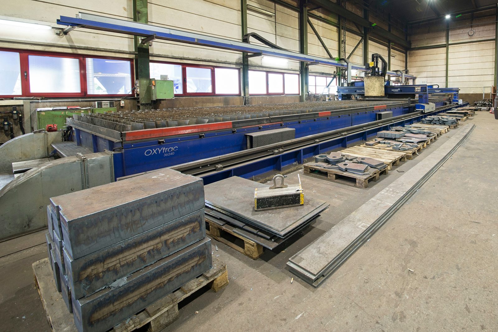
Below about 25 mm, oxy-fuel cutting is technically possible, but plasma is usually the more economical choice and introduces less heat into thin plate. A heavy-duty forklift and overhead crane handle the large plates before and after cutting.
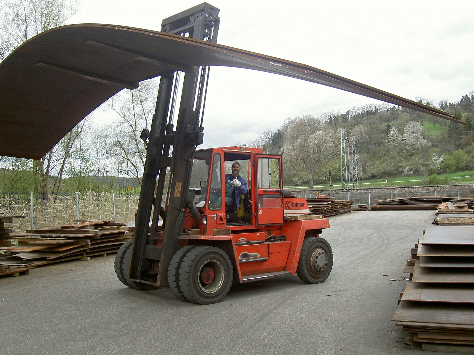
Planning the cut: nesting and cutting sequence
Before the machine starts, the program is created. From the drawing or DXF file, the contours are nested on the plate: material utilisation, web widths and the order of the cuts are part of the programming, not left to chance.
The cutting sequence is more than logistics – it is the first measure against distortion. Every cut brings heat into the plate; a sequence that distributes the stresses evenly saves straightening work later. This is also where it is decided where bevels are cut in the same pass and where a machining allowance is left for subsequent machining.
Preheating: when the material needs warming before cutting
Not every steel may be cut cold. With crack-sensitive materials, the whole component is brought up to temperature before cutting: this slows down cooling at the cut edge, keeps hardening within limits and prevents hardening cracks. This mainly affects wear-resistant steels such as Hardox and XAR as well as thick fine-grain structural steels – in other words, precisely the materials for which flame cutting otherwise pays off most.
Whether preheating is required, and to what temperature, depends on the material, the material thickness and the carbon equivalent. There is therefore no universally valid temperature: steel manufacturers give recommendations for their wear-resistant grades by grade and plate thickness, and the thicker and harder the plate, the more likely preheating is needed.
It is important to distinguish this from the next step, because the two terms are often confused: preheating concerns the whole workpiece and serves to prevent cracks. Initial heating concerns only the starting point and brings it to ignition temperature. The first depends on the material; the second happens with every cut.
Heating to ignition temperature
The heating flame of fuel gas and oxygen brings the starting point to ignition temperature – around 1,150 °C for structural steel, recognisable by the bright glow. Only once the material has reached that point can the actual reaction start.
Heating the starting point takes time. On thin plate, that time accounts for a larger share of the operation, while the advantages of oxy-fuel cutting become less significant.
The heating flame is fed by a fuel gas and oxygen. In oxy-fuel technology, acetylene is the most commonly used fuel gas; with oxygen it burns at around 3,100 °C and brings the starting point up to temperature correspondingly quickly. Liquefied gas such as propane, and natural gas, are used mainly for heating and flame cutting. The gas determines heating time and gas costs – the cut itself is always made by the oxygen jet.
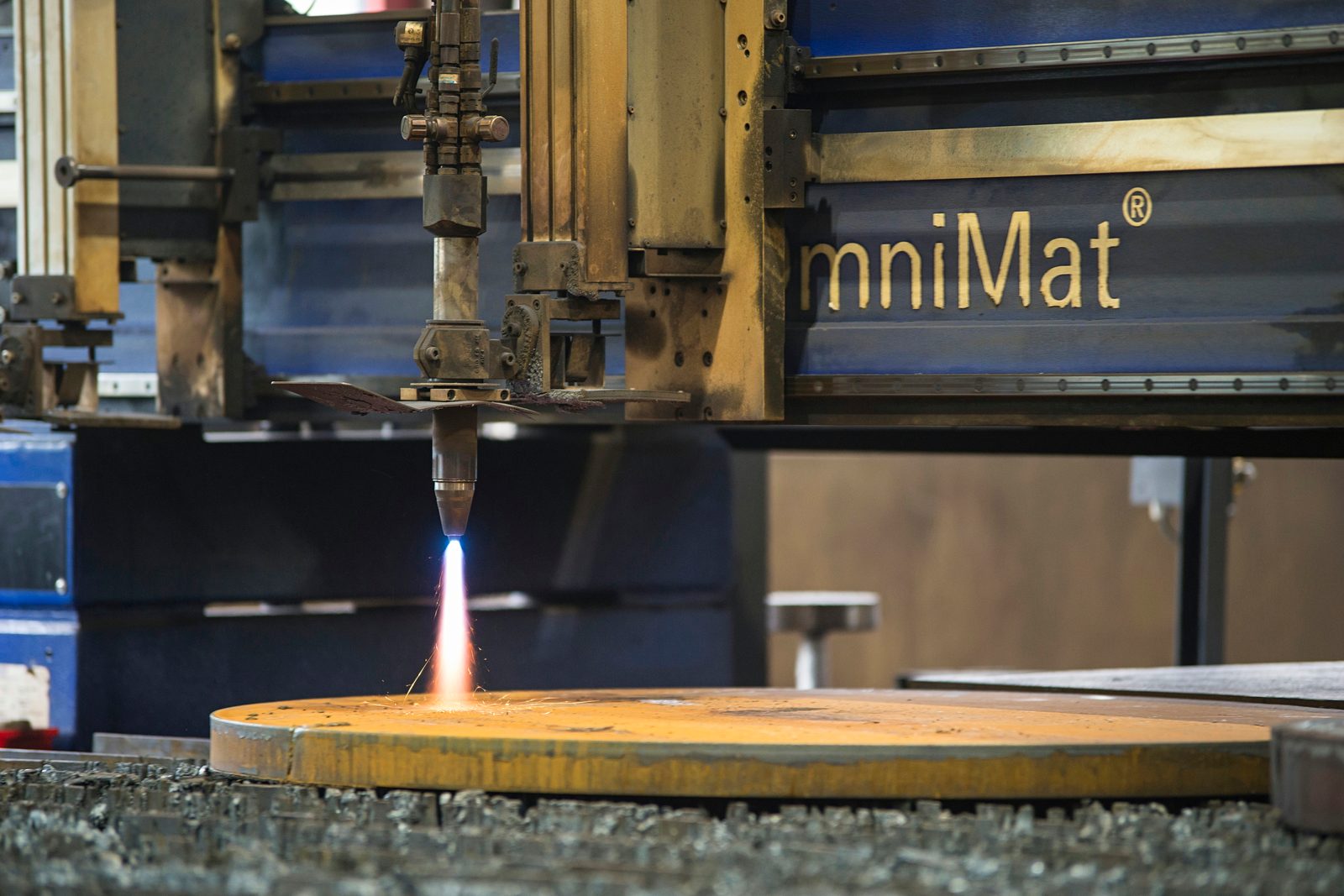
Piercing and starting the cut
At the ignition point the torch opens the cutting oxygen. The jet burns the iron into liquid slag and blows it downwards out of the kerf – from here on the process sustains itself, because the combustion of the iron supplies a large part of the heat.
Inner contours require a pierce through the full material thickness. On the CNC machine the piercing point is therefore deliberately placed next to the contour; from there the torch moves onto the line and only then follows the programmed path. This keeps the slag thrown up by the pierce outside the finished cut face.
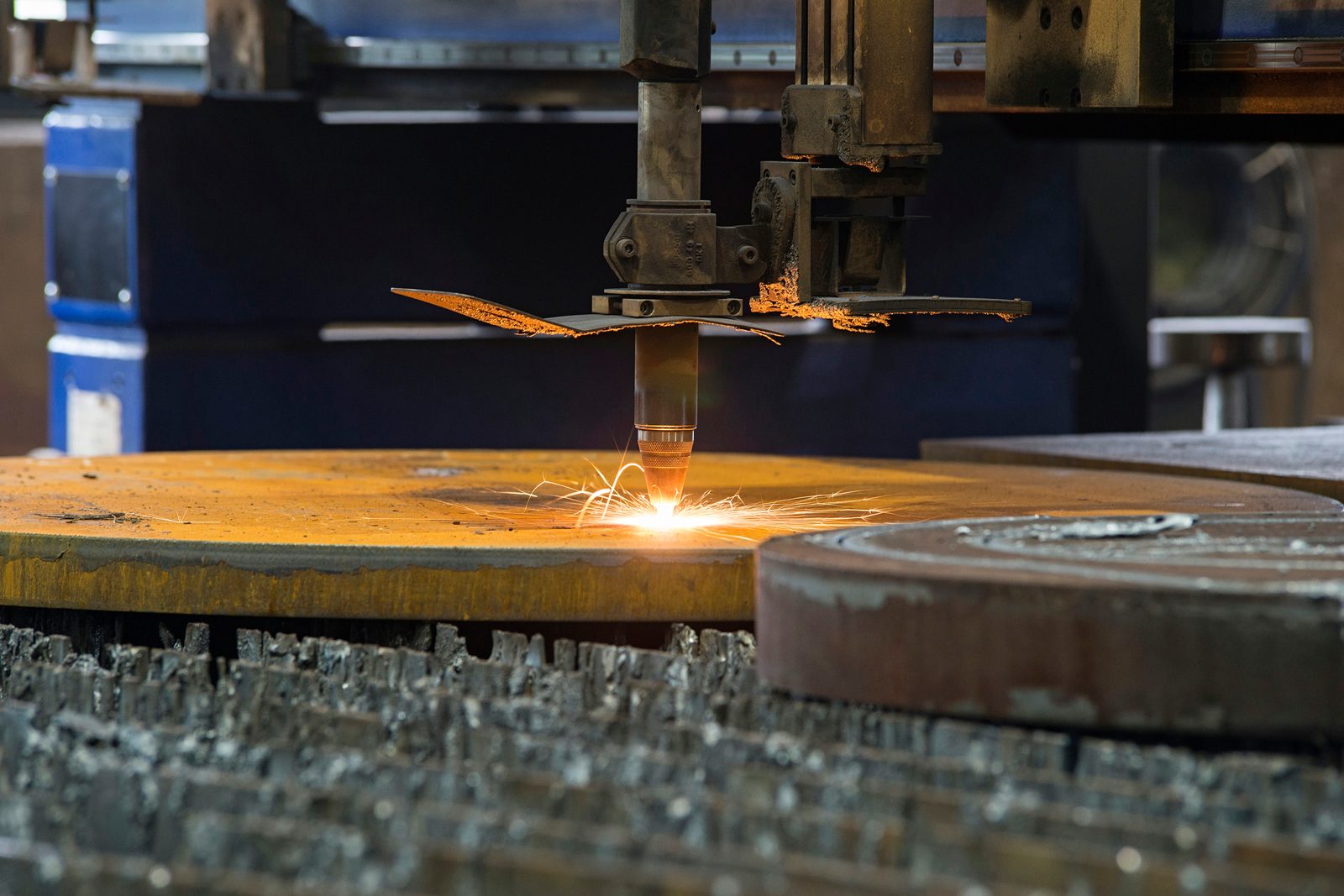
Controlling the cut: travel speed, nozzle stand-off and cutting oxygen
Three variables determine the cut face: feed rate, nozzle distance and oxygen pressure. On a CNC flame cutting machine they are controlled rather than guided by hand – the same across the entire contour and across the entire plate.
CNC control makes the torch path and cutting conditions repeatable along the contour and across successive parts. The operator still has to select suitable parameters and check the cut quality.
What is automated is precisely what the operator would have to track with a hand torch: the path via the CNC control, the distance between nozzle and plate via height control, plus ignition, heating and piercing according to the program. Our machine works with an oxy-fuel torch, height control and automatic piercing; machines for large series of identical parts also carry several torches on one gantry. What remains manual is the work preparation – nesting, cutting sequence, parameters per material and thickness – and the post-treatment of the edge.
Bevel cutting: weld preparation in the same setup
For welded structures, the bevel cut is what counts: a swivelling torch unit cuts the weld preparation up to ±45° at the same time. The bevel is thus produced in the same operation as the contour – a separate machining step is no longer needed.
For structures welded to DIN EN 1090-2 EXC3, the bevel establishes the joint geometry for welding. Planning it with the cutting operation helps deliver the required preparation to the fitting and welding stages.
After cutting: removing slag, finishing edges and marking parts
Cutting produces the blank. Before it moves on, three finishing and traceability steps follow:
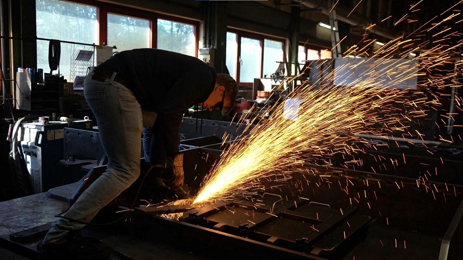
- Removing slag and scale: solidified melt hangs on the lower edge of the kerf, and a layer of scale sits on the cut face. Both are removed from every part – without this step a flame-cut blank cannot be processed further.
- Inspecting the edges: only then does the edge itself come into play. Minor residual burrs caused by the process are permissible; we carry out defined edge finishing, edge rounding or complete deburring if the drawing or the order specifies it.
- Transferring the marking: when a plate is divided, only the remnant plate still carries the original material marking. Re-stamping transfers material, heat number and sample number from the inspection certificate 3.1 to every single flame-cut part.
For load-bearing components and welds, reworking such as grinding or straightening is added where required. Corrosion protection – blasting, priming, coating – is not standard, however, and is only carried out if expressly ordered; without such an agreement, mill scale and scale on the plate surface are permissible.
Further processing: from blank to assembly
The parts then go straight on to the next production stage – rolling, bending, welding, machining, blasting and painting. The flame-cut blank is a thermal rough blank; fits and functional surfaces are produced afterwards by CNC machining, and the blank is given a machining allowance for this.
Whatever has already been built into the blank carries through into forming: a bevel produced in the flame cut is cut on the flat plate and, after bending, runs unchanged along the entire edge. The weld preparation is therefore complete before the component takes its shape.
If residual stress from the heat input remains in the component, it can be relieved in a targeted way before machining – without a furnace, by vibration stress relief. That is the practical reason for manufacturing under one roof: whoever does the cutting knows what comes next.
Cut quality to EN ISO 9013
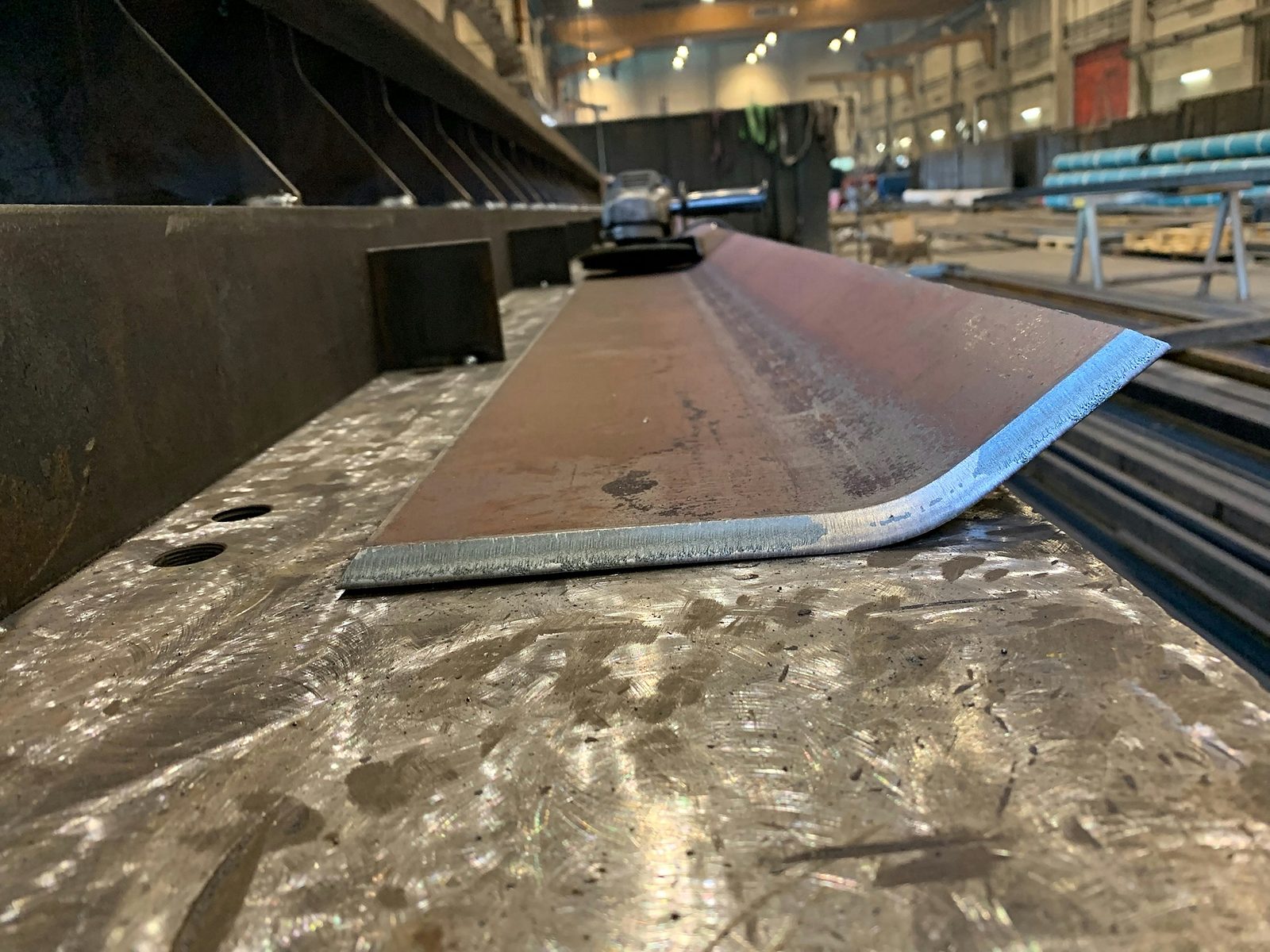
The quality of a flame cut is assessed to EN ISO 9013 – by perpendicularity or angularity tolerance and the mean height of the profile of the cut face. When properly controlled, oxy-fuel flame cutting produces perpendicular, smooth cut faces that can be processed further directly.
This does not automatically guarantee a particular tolerance or quality class: it is agreed when the component needs it. For typical steel construction blanks, the achievable accuracy is sufficient without a separate agreement.
If a cut face deviates, the cause can usually be read from the defect pattern. Which irregularities occur in oxy-fuel flame cutting of unalloyed and low-alloy steels, and what causes them, is set out in table form in the DVS 2102 technical bulletin (DVS: German Welding Society).
Limits – when flame cutting is not the right choice
In these cases another process is better than oxy-fuel flame cutting:
- Stainless steel: the chromium oxide layer prevents the iron from burning in the oxygen jet – stainless steel is therefore cut with plasma.
- Aluminium: contains no combustible iron and forms an oxide layer with a high melting point – fundamentally unsuitable for oxy-fuel cutting.
- Plates below about 25 mm: technically feasible, but slower than plasma and prone to distortion because of the heat input.
- Very fine contours and small holes: the kerf and the heating zone set geometric limits – small precision holes are better produced by machining.
- Tight tolerances on functional surfaces: a flame-cut blank is a thermal rough blank; fits are produced in the subsequent CNC machining.
These limits are the reason why a cutting partner needs several processes under one roof – and chooses the most economical one for each component.
How thick a steel plate can flame cutting handle?
The process itself sets hardly any upper limit, because the combustion of the iron supplies the heat in the cut. The quality standard DIN EN ISO 9013 classifies flame cuts from 3 to 300 mm thickness; special machines also cut beyond that, but then outside the standardised range.
In practice, the limit is set by the machine: the torch, gas supply and table must be able to handle the thickness. At Bock it is 200 mm, and we also cut up to this thickness in practice – on the machine described in the chapter Flame cutting in practice. At the lower end the limit is economic, not physical: below about 25 mm, plasma cutting is faster and introduces less heat.
The permissible deviation also grows with thickness. The EN ISO 9013 tolerances for perpendicularity and profile height are graded by cut thickness – a 150 mm edge may deviate more than a 30 mm edge of the same quality class.
Flame cutting or plasma cutting?
The two processes complement each other – material and material thickness decide:
| Criterion | Oxy-fuel flame cutting | CNC plasma cutting |
|---|---|---|
| Operating principle | Burning in the oxygen jet | Melting in the plasma arc |
| Material thickness | from approx. 25 mm up to 200 mm | up to approx. 60 mm |
| Materials | unalloyed and low-alloy steel | stainless steel as well |
| Speed | economical at large thicknesses | considerably faster on thin plates |
| Heat input | higher – generous heating zone | lower – less distortion on thin plate |
Rule of thumb: below 25 mm or alloyed material – plasma. From 25 mm in unalloyed or low-alloy steel – flame cutting, and the thicker the plate, the clearer the choice.
Flame cutting in practice – machines and workflow at Bock
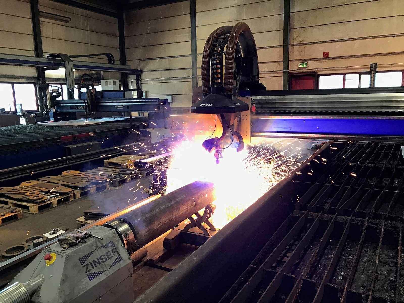
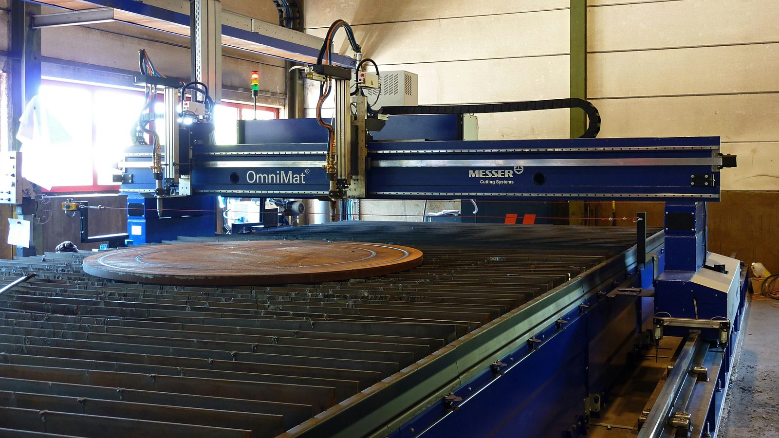
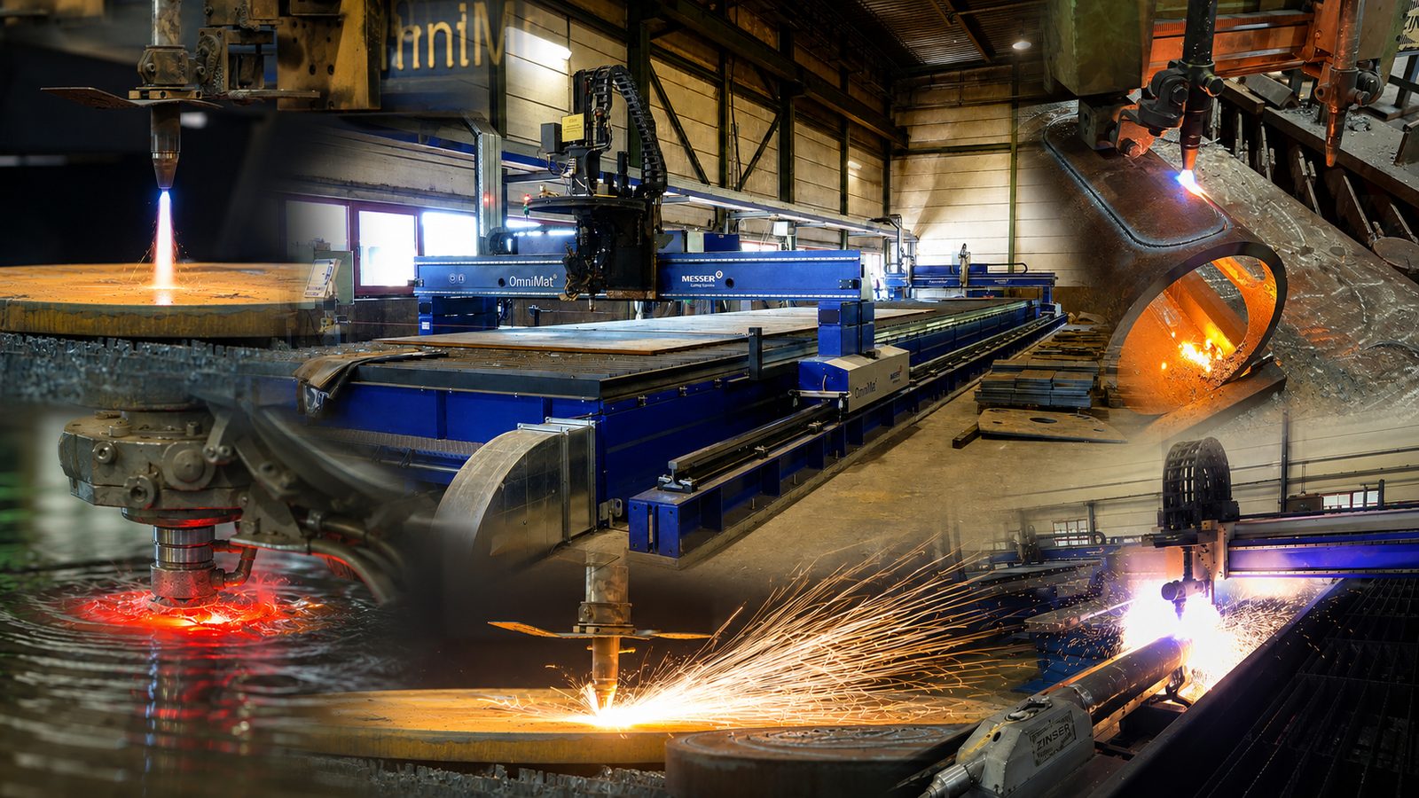
In our contract manufacturing in Lorch in the Stuttgart region, oxy-fuel flame cutting runs on a Messer OmniMat L5000 with a table area of 20,000 × 3,500 mm: large-format plates, material thicknesses up to 200 mm, bevel unit up to ±45°. The plasma torch sits on the same machine – which of the two processes a part gets is decided per order, not per machine. Details of all machines are shown on the machinery page.
The difference from a pure cutting shop lies in the surroundings: our own stock of more than 40 material grades including inspection certificate 3.1 to EN 10204, a welding supervision (IWE/EWE) that treats flame-cut blanks as weld preparation from the start, and the complete further processing – rolling, welding to DIN EN 1090-2 EXC3, CNC machining, blasting and painting – under one roof.
Oxy-fuel cutting for pipes and sections
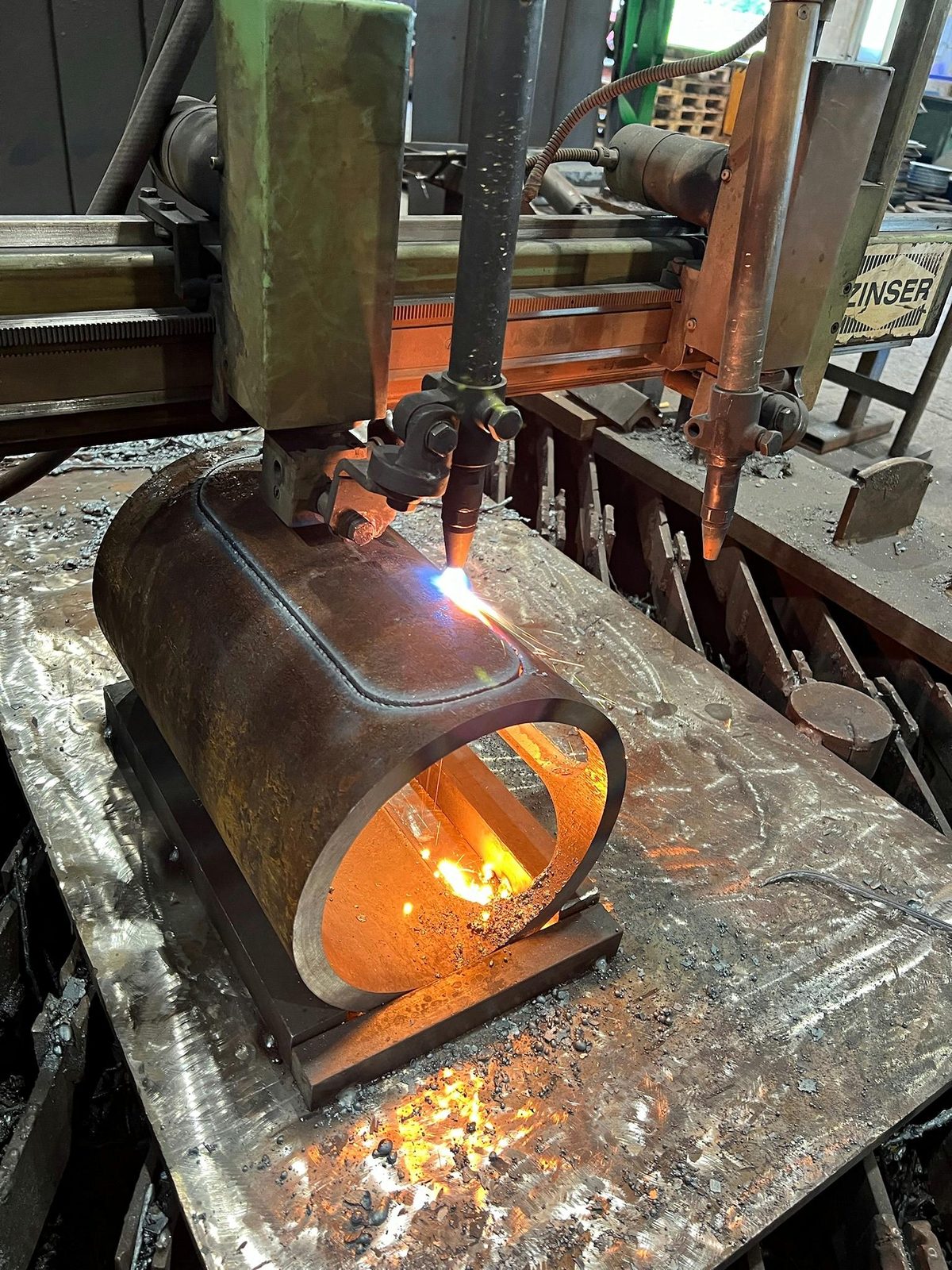
Alongside the plate machine runs a second line: a Zinser copy flame cutting machine cuts pipes with wall thicknesses up to 50 mm. Intersections, notches and pipe contours are produced there by oxy-fuel cutting – the powerful alternative to the tube laser when the wall gets thick.
Thinner-walled pipes and alloyed materials are handled instead by 3D plasma cutting. As with plate, the decision is made by material and wall thickness, not by habit.
Examples: finished flame-cut blanks
Examples from the workshop – long flame-cut parts in S355, thick-walled rings with a burnt-out inner diameter, straps with holes and blanks with a stepped contour from heavy plate, as well as a mixed batch of finished blanks on pallets: circular blanks, flat parts with bevels and contour parts in various plate thicknesses. The cut faces show the drag lines from which the cut quality to EN ISO 9013 can be read.
From plate to flame-cut blank in pictures
Revisit the workshop images from this article. Select an image to return to its chapter.
-
The flame-cut blank -
2 Which materials can be oxy-fuel cut? -
5 Heating to ignition temperature -
6 Piercing and starting the cut -
7 Controlling the cut: travel speed, nozzle stand-off and cutting oxygen -
8 Bevel cutting: weld preparation in the same setup -
9 After cutting: removing slag, finishing edges and marking parts -
10 Further processing: from blank to assembly -
15 Flame cutting in practice – machines and workflow at Bock -
16 Oxy-fuel cutting for pipes and sections
Frequently asked questions about flame cutting
Which material thicknesses can be flame cut economically?
As a rule of thumb, from about 25 mm upwards; our equipment cuts up to 200 mm. Below that, CNC plasma cutting usually takes over – it is faster on thin plates and introduces less heat.
What temperature does flame cutting need?
The starting point has to reach ignition temperature – around 1,150 °C for structural steel; the heating flame that takes it there is around 3,100 °C hot with acetylene and oxygen. Only at ignition temperature does the cutting oxygen open and burn the iron. What matters is not the melting point but that the ignition temperature lies below it and that the oxides run off as a liquid; this is where the process fails with stainless steel, aluminium and cast iron.
What is the difference between preheating and initial heating?
They are two different steps that are often confused. Preheating concerns the whole workpiece and takes place before the cut – it slows down cooling of the cut edge and, in crack-sensitive materials such as Hardox or thick fine-grain steels, prevents hardening cracks. Initial heating concerns only the starting point and brings it to ignition temperature with the heating flame; this happens with every flame cut.
How can cracking be avoided in oxy-fuel cutting?
Cracks on the flame-cut edge are almost always hardening cracks: the narrow zone next to the kerf cools very quickly, hardens in the process and cracks under residual stress. The most effective remedy is preheating the whole workpiece – it slows down cooling and keeps hardening within limits. In addition, a cutting sequence that distributes the heat evenly across the plate helps, as does slow cooling in still air instead of quenching or draughts. Wear-resistant steels such as Hardox and XAR and thick fine-grain structural steels are particularly crack-sensitive; whether they are preheated, and to what temperature, depends on grade and plate thickness – the steel manufacturers give recommendations for this.
Why can stainless steel not be oxy-fuel cut?
Oxy-fuel flame cutting is based on the combustion of iron in the oxygen jet. The chromium oxide layer of stainless steel prevents precisely this reaction – the cut does not happen. Stainless steel is therefore cut with plasma.
What is the difference between flame cutting and oxy-fuel cutting?
None – both terms describe the same process: cutting with a fuel gas–oxygen flame and cutting oxygen. Gas cutting and oxygen cutting also refer to the same process.
What is the difference between a flame cut and a flame-cut blank?
The flame cut is the cut face; the flame-cut blank is the finished part. A flame-cut blank is always a thermal rough blank – fits and functional surfaces are produced afterwards by CNC machining, and the part is given a machining allowance for this.
Does the material distort during flame cutting?
The heat input creates residual stresses; the thinner the plate, the more likely distortion becomes visible. In practice, a well-planned cutting sequence and clean nesting limit the effect. With thick plates from 25 mm, distortion rarely plays a role.
Do I need to have my flame-cut parts deburred?
The flame-cut edge never comes out of the machine finished: solidified slag hangs on the lower edge of the kerf, and a layer of scale sits on the cut face. Both have to be removed before the part can be processed further or installed – that is why at Bock this step is part of the cutting and does not have to be ordered separately. Only what goes beyond it needs to be agreed: defined edge finishing, edge rounding or complete deburring to drawing. Ideally, mention this right away in your enquiry – then it becomes part of the quotation.
Is the material marking retained after cutting?
Yes, seamlessly on request. When a plate is divided, only the remnant plate still carries the original marking. Re-stamping transfers material, heat number and sample number from the inspection certificate 3.1 to EN 10204 to every single flame-cut part.
How dimensionally accurate is a flame-cut blank?
Flame cuts are classified to EN ISO 9013; for typical steel construction blanks, the achievable accuracy is fully sufficient. Fits and functional dimensions are produced afterwards by CNC machining – the blank is given a machining allowance for this.
Sources and standards on flame cutting
Each entry states which statement it supports. Standards are named with number and edition; their text is subject to a charge and is therefore not linked. Editions of standards checked on 5 October 2026 – for an order, the agreed edition applies. The linked source was accessed and read on the date stated.
- Quality characteristics of a flame cut (perpendicularity or angularity tolerance, mean height of the profile), graded by cut thickness; scope for flame cuts from 3 to 300 mm DIN EN ISO 9013 – Thermal cutting – Classification of thermal cuts – Geometrical product specification and quality
- Classification of thermal cutting processes; oxy-fuel flame cutting as a process in its own right alongside plasma and laser cutting DIN 2310-6 – Thermal cutting – Part 6 – Classification, processes
- Defect patterns on the cut face and their causes Merkblatt DVS 2102 (technical bulletin) – Irregularities and their causes in oxy-fuel flame cutting of unalloyed and low-alloy steels
- Inspection certificate 3.1 as the origin of the material marking DIN EN 10204 – Metallic products – Types of inspection documents
- Execution class EXC3 for the subsequent welded structure DIN EN 1090-2 – Technical requirements for the execution of steel structures
- Acetylene as the most commonly used fuel gas, around 3,100 °C with oxygen (section 3.2.1); liquefied gas and natural gas mainly for heating and flame cutting (section 3) DGUV Information 209-011 (guidance of the German Social Accident Insurance) – Gasschweißen (gas welding), edition October 2018