Weld testing methods: what they detect and when to use them
Contents
The drawing calls for testing – but which kind?
A drawing may call for “non-destructive testing of welds” or “quality level B to EN ISO 5817” without naming a method. To turn that requirement into a test plan, the material, weld type, thickness and target irregularities must also be known.
Anyone who specifies the wrong method can receive a tidy report and still miss the testing objective. MT cannot be applied to an austenitic stainless steel weld because the material is not ferromagnetic. PT does not find a lack of fusion that has no connection to the surface. What matters, therefore, is which irregularity can be detected with the chosen technique under the actual testing conditions.
This article explains the six common methods VT, PT, MT, ET, UT and RT. The selection is governed by DIN EN ISO 17635:2025-08 (general rules for non-destructive testing of welds); the editions of the standards and the associated primary sources are listed in the sources section. The focus is on welded steel assemblies. For other materials, the acceptance standards must also match the material.
The six methods at a glance
The short version first – each method with its detection limit and the two standards that govern it: one for how the test is carried out, one for the question of when an indication becomes unacceptable.
| Method | What it detects | Key limitation | Standards |
|---|---|---|---|
| VT – visual testing | Visible irregularities on the surface: weld geometry, undercuts, open cracks, pores, spatter, linear misalignment | Only what the eye can reach (with a magnifier, endoscope or weld gauge if needed) – no information below the surface | Testing ISO 17637 · Assessment ISO 5817 |
| PT – penetrant testing | Flaws open to the surface: cracks, pores, lack of fusion connected to the surface – on all non-porous materials | The flaw must reach the surface. A closed crack below the weld remains invisible | Testing ISO 3452-1 · Acceptance ISO 23277 |
| MT – magnetic particle testing | Surface cracks and near-surface irregularities; detection depends, among other things, on position and direction of magnetisation | Ferromagnetic materials only (unalloyed and low-alloy steels, ferritic and duplex stainless steels). Unusable on austenitic stainless steel | Testing ISO 17638 · Acceptance ISO 23278 |
| ET – eddy current testing | Near-surface irregularities in electrically conductive materials; weld testing to ISO 17643 mainly on ferritic materials | Low penetration depth; changes in geometry and microstructure produce spurious indications; the only method without a paired ISO acceptance standard | Testing ISO 17643 · Acceptance to be agreed contractually |
| UT – ultrasonic testing | Internal planar irregularities: lack of fusion, cracks, laminations – the strength of the method lies in planar flaws | Probe must couple and reach the test volume; ISO 17640 describes manual testing from 8 mm thickness with low sound attenuation | Testing ISO 17640 · Acceptance ISO 11666 |
| RT – radiographic testing | Internal volumetric irregularities: pores, wormholes, inclusions – provides a visual image of the weld | Radiation protection and suitable exposure geometry required; narrow planar flaws may be shown faintly or not at all if unfavourably oriented | Testing ISO 17636-1/-2 · Acceptance ISO 10675-1 |
The location of the testing objective decides: surface methods do not replace volumetric testing. UT and RT are not freely interchangeable either – flaw orientation, material and geometry determine which technique is suitable.
Choosing a method for the inspection task
These cases show the direction of selection. They do not replace a component-specific test plan; the agreed specification and the actual testability decide.
| Testing task | Selection direction | Clarify before ordering |
|---|---|---|
| Weld shape and visible irregularities | VT | Is the entire required surface accessible and adequately prepared? |
| Surface-breaking cracks on austenitic stainless steel | PT | Is the surface suitable and free of coating? MT is ruled out for this material. |
| Surface cracks on ferromagnetic structural steel | MT, PT if specified | Which field directions and surface conditions does the test procedure require? |
| Internal lack of fusion in a full-penetration steel butt weld | Suitable UT technique | Do the beam angle and coupling surfaces reach the required test volume? |
| Pores or inclusions inside the weld | RT or suitable UT technique depending on testing objective | Which detection sensitivity and documentation are required? |
| Crack detection on an already coated structure | Consider ET; MT only if suitability is proven | Define material, coating, reference block and acceptance criteria. |
Fillet welds and butt welds cannot be tested in the same way. “100 % UT” is only a robust requirement if the designated weld volume can actually be examined with a suitable technique.
VT – visual testing: weld shape and accessible surface
Visual testing to DIN EN ISO 17637 is the foundation of weld testing. It assesses the accessible surface and the weld geometry; for steel structures to DIN EN 1090-2 (execution of steel structures), all welds must be visually inspected over their entire length.
Testing is done with the naked eye and, where necessary, with a magnifier, endoscope, mirror and weld gauge. The inspector assesses excess weld metal and weld shape, undercuts, open cracks and pores, linear misalignment, weld spatter, crater cracks and whether the weld has been completed at all. Adequate lighting and a viewing distance specified by the standard are prerequisites.
Visual testing is scheduled before coating. Paint can conceal fine surface irregularities. Blasting, on the other hand, does not automatically rule it out: what matters is that the surface remains suitable, clean and accessible for the intended test.
PT – penetrant testing: detecting surface-breaking flaws
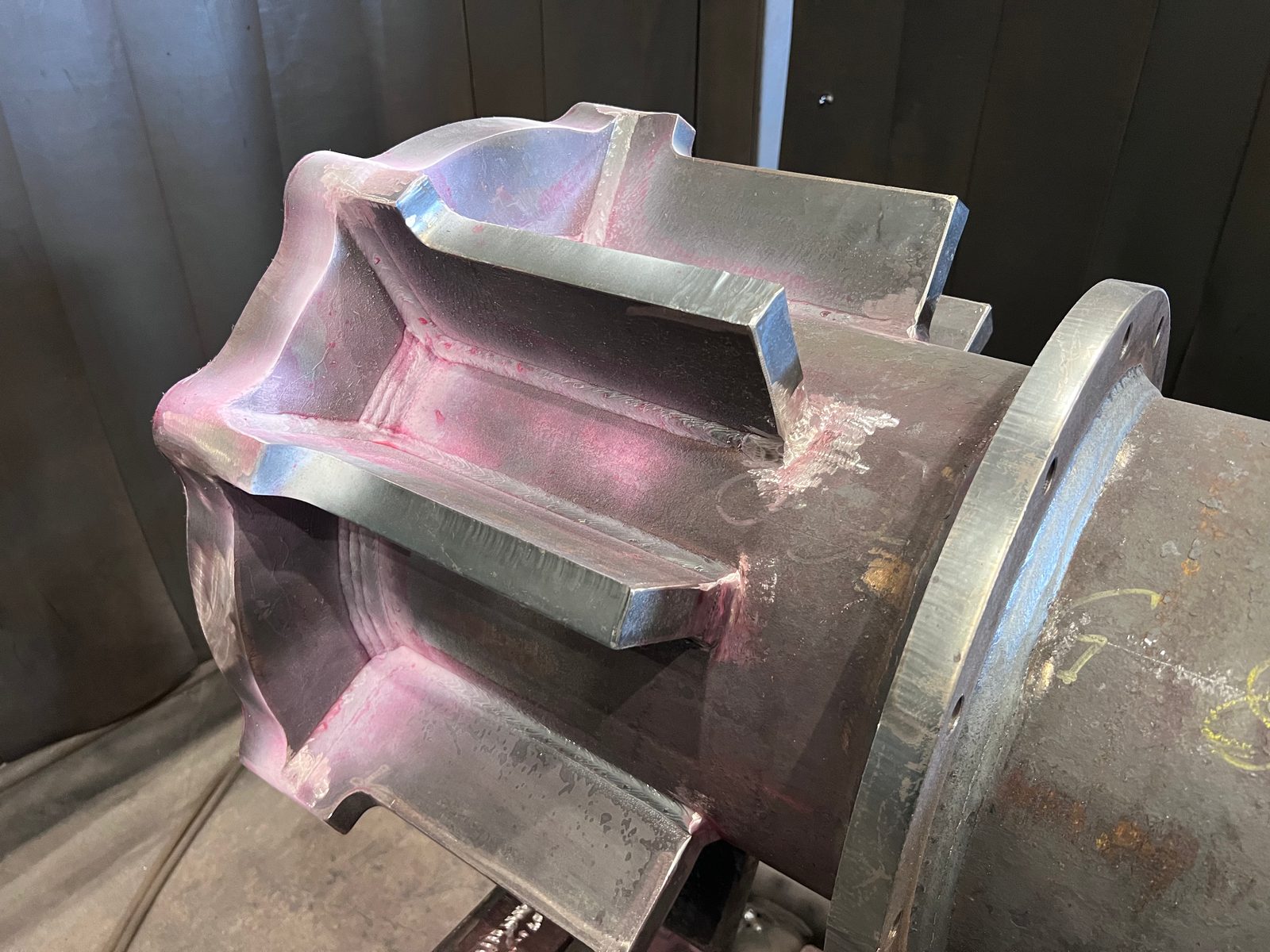
Dye penetrant testing – in German workshops usually called the “red-white test” (Rot-Weiß-Prüfung), after the red penetrant and the white developer – makes flaws visible that are open to the surface. The method works by capillary action and follows a fixed sequence:
- Cleaning and pre-treatment – the weld must be free of scale, grease and paint residues, otherwise you are testing the contamination instead of the weld.
- Applying the penetrant and leaving it to act as specified in the test procedure – capillary action draws it into accessible, surface-breaking flaws.
- Intermediate cleaning – excess penetrant is removed from the surface without washing it out of the flaws. This step determines how meaningful the entire test is.
- Applying the developer – the thin white layer draws the penetrant out of the flaw back to the surface and widens the indication until it can be assessed by eye. This produces the image by which the method is recognised in the plant: a red line or dot on a white background.
- Assessing and documenting – the type, position and length of the indication are evaluated against the acceptance levels of DIN EN ISO 23277.
PT is also suitable for austenitic stainless steel and aluminium, provided the surface and material are compatible with the testing product system. Porous surfaces, residues or smeared-over crack openings can impair the test. A flaw lying completely below the surface remains invisible. The fluorescent variant works with a different product system and suitable UV-A lighting; it is not assessed by the red dye.
MT – magnetic particle testing: on ferromagnetic materials only
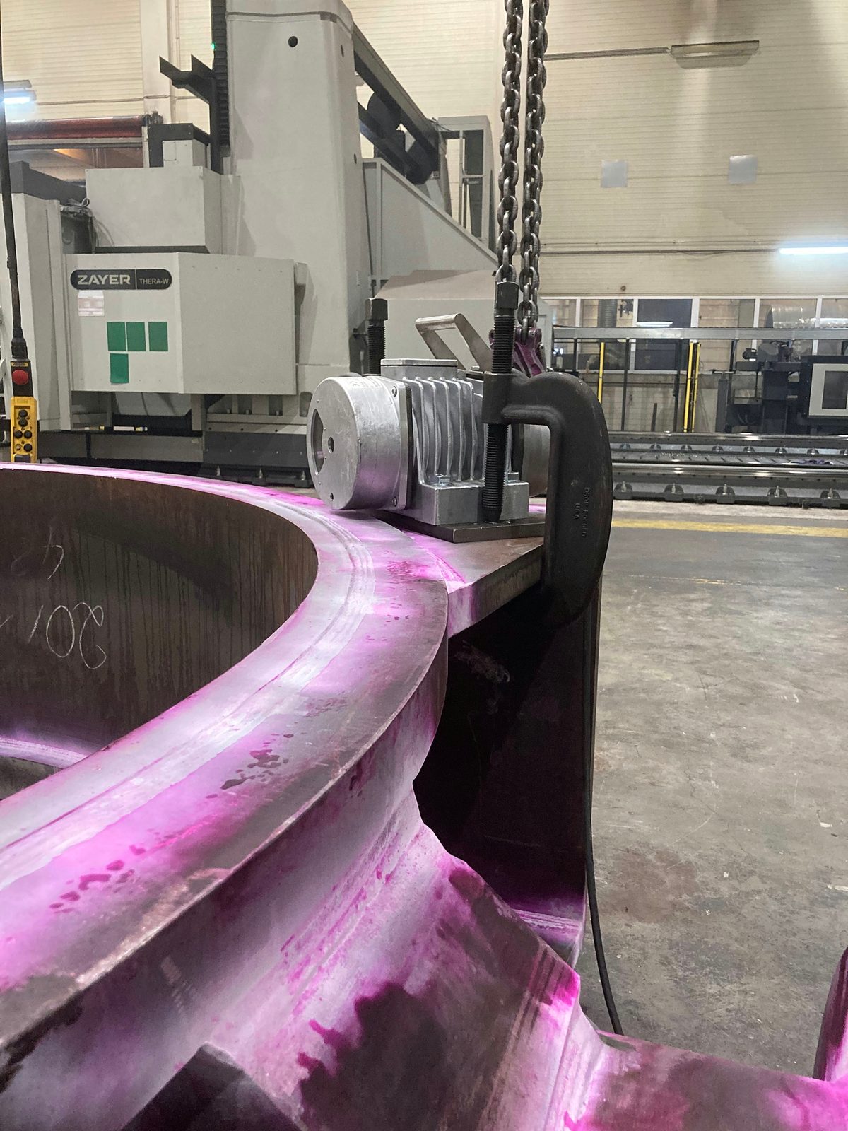
In MT to DIN EN ISO 17638, the component is magnetised. An irregularity can create a leakage field at which magnetic testing particles accumulate. Depending on the product system, the indication is assessed in visible light or under UV-A lighting.
- MT is particularly suitable for fine surface cracks and can also indicate near-surface irregularities. A fixed detection depth cannot be derived from this: flaw position, field direction and testing conditions interact.
- This is offset by a hard restriction that no amount of testing care can overcome: the method works exclusively on ferromagnetic materials. Unalloyed and low-alloy structural steels are suitable, as are ferritic and duplex stainless steels; austenitic stainless steels, aluminium and copper alloys are not. If the drawing calls for MT on an austenitic stainless steel weld, that is an error in the specification – and the right time to clarify it is before manufacturing.
Magnetisation direction affects sensitivity. Cracks crossing the magnetic field are more readily detected than cracks parallel to it, so test procedures usually specify two approximately perpendicular directions. Omitting a direction can leave some flaws undetected.
ET – eddy current testing: inspecting through suitable coatings
In eddy current testing to DIN EN ISO 17643, a coil carrying an electric current generates an alternating magnetic field that induces eddy currents in the component. An irregularity disturbs their flow, and this disturbance acts back on the coil. The change is evaluated in magnitude and phase – hence the full title of the standard, “Eddy current testing of welds by complex-plane analysis”.
- ET requires an electrically conductive material; weld testing to DIN EN ISO 17643 is aimed mainly at ferritic materials. It needs neither penetrant nor developer. Thin non-conductive coatings can remain on the component under suitable testing conditions. Coating thickness and probe distance influence the signal and must be taken into account during setup and evaluation.
- This is an advantage for recurring inspections of coated structures. It does not, however, mean blanket suitability for every painted weld, nor interchangeability with MT. Where ET is required, the testing objective, surface condition, reference block and evaluation are clarified in advance; another method is used only by agreement.
Eddy currents penetrate only a shallow depth, which decreases as frequency rises. Weld toes, gaps and changes in geometry or microstructure can also affect the signal, so experienced personnel must distinguish these effects from flaws. Unlike PT, MT, UT and RT, weld testing by ET has no dedicated ISO acceptance-level standard. Its evaluation criteria must therefore come from the applicable specification or an agreement between the parties.
UT – ultrasonic testing: detecting internal flaws
In UT to DIN EN ISO 17640, a probe couples sound waves into the component. Interfaces and irregularities can produce echoes. Time of flight and signal behaviour help to locate and evaluate indications; their amplitude is not a direct measure of the true flaw size.
- Planar irregularities such as lack of fusion and cracks can be readily detectable with UT if the sound strikes them at a suitable angle. An unfavourable orientation can make detection more difficult. UT requires no ionising radiation; depending on the weld and test plan, access from one side is sufficient, but the probe needs enough space on the coupling surface.
- DIN EN ISO 17640 describes the manual testing of fusion-welded joints from 8 mm thickness with low ultrasonic attenuation. That is the scope of this standard, not a physical lower limit of all ultrasonic techniques. Thinner parts, coarse-grained or austenitic microstructures and difficult geometries require a separately suitable technique. A conventional echo display is interpreted by the inspection personnel; other ultrasonic techniques can additionally provide imaging and storable data.
The applicable acceptance levels are defined for the agreed task, in the scope covered here to DIN EN ISO 11666. Testing level and acceptance level serve different purposes – one describes the test, the other the evaluation.
RT – radiographic testing: imaging the weld interior
RT uses X-rays or gamma rays to record differences in the penetrated material thickness. DIN EN ISO 17636-1 describes the film technique, Part 2 the technique with digital detectors. Both provide a documentable projection of the irradiated area.
- Pores and inclusions can be shown well with suitable exposure geometry. The image makes the finding easier to trace later. Whether RT or UT is required is nevertheless decided by the testing task and not solely by the wish for an archived result.
- Narrow planar flaws can appear faintly or not at all if their angle to the beam is unfavourable. RT is therefore not a general substitute for UT. Added to this is the organisation of radiation protection: exposure location, accessibility and a secured testing area must suit the component and the production sequence.
- At Bock, RT is carried out via qualified partners. Whether the component is transported to the testing service provider or testing on site is possible is agreed on a project basis. The appointment for it is scheduled before production is completed.
For steel, nickel, titanium and their alloys, DIN EN ISO 10675-1 specifies the acceptance levels. They are not a general basis for evaluating every metal.
Which standard decides which method is required?
DIN EN ISO 17635:2025-08 links testing task, method, testing technique and evaluation. The requirement to test comes from the applicable application standard or the agreed specification. The selection follows these parameters:
- Material and microstructure – MT needs ferromagnetism, ET electrical conductivity. Sound attenuation and microstructure affect the suitability of UT.
- Weld type and access – a fillet weld can be tested differently from a full-penetration butt weld. UT requires coupling surfaces; RT a suitable arrangement of radiation source and detector.
- Thickness and welding process – they influence suitable techniques and the irregularities to be expected. The scope of the respective testing standard must be observed.
- Testing objective and scope – surface or weld interior, planar or volumetric irregularity, which weld areas and what proportion. Accessibility alone does not decide the selection.
In practice, a single method is rarely required, but rather a combination – typically full-coverage visual testing, supplemented by a surface method on the critical welds and, where the weld quality demands it, a volumetric method on a defined testing proportion.
Why quality level B alone does not define the inspection requirements
An indication is initially a signal or a visible accumulation of testing medium. It has to be classified: relevant to the testing task, or caused by geometry and testing conditions? Only then is the relevant indication evaluated against the defined acceptance levels.
DIN EN ISO 6520-1 names geometric irregularities. DIN EN ISO 5817 assigns their permissible extent to quality levels B, C and D; B sets the most stringent requirements. Its scope covers fusion-welded joints in steel, nickel, titanium and their alloys, excluding beam welding. The levels are not a general approval for every material and every type of loading.
“Quality level B to EN ISO 5817” names the required quality level. Method, testing technique, testing proportion and the evaluation of method-specific indications remain open. ISO 17635 expressly states that acceptance levels cannot be read directly from the quality levels; it provides the correlations for specific techniques.
For PT, ISO 23277 specifies the acceptance levels, for MT ISO 23278, for UT ISO 11666 and for RT on the materials named ISO 10675-1. For ET, the evaluation criteria must be defined from the applicable specification or an explicit agreement. Anyone who simply orders “test the welds” leaves both the testing objective and the acceptance criterion open.
Specifying the inspection: what to agree before manufacturing
Quotation, manufacturing and acceptance need more than a method abbreviation. The following information makes the order traceable:
- Component and welds – drawing number, revision status, weld identification and the areas to be examined. Every weld must be traceable to the later report.
- Material and geometry – material designation, thickness, weld shape, accessible sides and any existing coatings.
- Basis of requirements – applicable application standard with agreed edition, EXC (execution class) and quality specifications where relevant. The current catalogue edition does not automatically replace the contractually specified edition.
- Testing and scope – method, technique or testing level, proportion, reference quantity and selection of test locations. Name surface and volumetric testing separately.
- Evaluation – appropriate acceptance standard and acceptance levels; for additional customer requirements, record the deviation explicitly.
- Timing and documentation – condition at testing, required waiting time or heat treatment, scope of documentation and procedure for unacceptable indications.
Example of the structure, not a ready-made standard specification: “Welds N1 to N4 as per drawing and revision; VT over the entire length; supplementary NDT as per attached test plan with method, scope, testing level and acceptance levels; testing in the specified surface condition; reports with weld reference.” This keeps the information that still has to be determined technically visible.
When is testing done – and why not immediately?
The timing of the test is not a formality. With certain materials and wall thicknesses, cracks can form with a delay – hydrogen-induced cold cracks only appear hours to days after welding, once the component has cooled and the hydrogen diffuses in the microstructure. A test immediately after welding would not find them.
The required waiting time follows from the material, the welding conditions and the applicable specification. A uniform number of hours for every weld would be wrong. The test plan also takes into account any required heat treatments and the condition at final testing.
Preparation and coating are separate steps. PT requires accessible crack openings; paint must be removed there. Blasting or grinding can prepare the surface, but can also clog fine openings. With MT, testing through a thin coating depends on the specified conditions and proof of sensitivity. That is why the suitable testing condition is agreed in advance and, in new fabrication, testing is scheduled before the final coating.
Personnel qualifications: DIN EN ISO 9712 and the former DIN EN 473
The qualification and certification of personnel for non-destructive testing is governed by DIN EN ISO 9712. It defines three levels: Level 1 may carry out tests according to written instructions and record the results. Level 2 may additionally prepare test procedures, select the method, assess and document results independently – this is the level that carries the actual testing responsibility in production. Level 3 is responsible for testing systems, methods and personnel.
- Certification applies to specific methods and sectors; a PT certification does not cover MT testing. In addition, the inspection personnel need task-specific authorisation from the employer. A valid certificate, the required proof of visual acuity and in-house approval must therefore be checked separately. Certification alone does not yet constitute a specific testing order.
DIN EN 473 is the withdrawn predecessor standard; DIN EN ISO 9712 has applied in its place since 2012. An old drawing requirement citing EN 473 is checked against the qualification requirements that apply today. An old certificate does not automatically become valid through the new standard designation. The requirements for simple direct visual inspections must also be distinguished according to the respective application standard; not every visual check automatically requires ISO 9712 certification.
Testing scope under DIN EN 1090-2
For steel structures within the scope of DIN EN 1090-2, the execution class and the execution specification are among the foundations of the test plan. However, this does not result in a universal percentage for all welds of a class:
- Visual testing – all welds are visually inspected over their entire length. A supplementary sampling proportion does not reduce this visual testing.
- Supplementary NDT – the scope is defined for the weld type and loading concerned in accordance with the applicable edition of the standard and the specification. EXC alone describes neither all test locations nor every required technique.
- Reference quantity – a percentage needs a clearly defined population and selection rule. “10 %” without reference to defined weld groups and test lengths leaves open what is to be tested.
- Additional requirements – special loading, the production situation or a finding can make further tests necessary. Test planning must take these requirements into account.
The designation “EXC3” replaces neither the weld list nor the test plan. DIN EN 1090-2 is, moreover, a standard for steel structures; its testing scopes do not automatically apply to every assembly in mechanical engineering. There, the applicable product standards and agreed requirements form the basis.
What non-destructive testing cannot do
Non-destructive testing assesses the weld that has been made. Three limits matter when specifying and interpreting it:
- It does not prove freedom from defects. Every method has a detection limit; below it, a flaw remains undetected. A passed test report means “no unacceptable indication found”, not “defect-free”.
- It does not replace procedure qualification. A weld produced without a qualified welding procedure specification, without a qualified welder and without suitable welding supervision does not become standard-compliant through subsequent testing – quality is created in the process, testing only confirms it.
- It does not turn a sample into full testing. There is no individual test result for an untested weld section. Whether a finding triggers additional tests on the production lot depends on the applicable specification.
Planned early and matched to the inspection objective, non-destructive testing provides documented evidence from the actual component. Its value depends on a suitable method, a defined scope and agreed acceptance criteria.
Reading a test report: indications, weld identification and retesting
The following checklist helps with acceptance. It does not replace the method-specific requirements for the test report:
- Identity – do the component number, drawing revision and weld identification belong to the part delivered?
- Execution – are the method, test procedure, testing standard, testing conditions and the scope actually examined traceable?
- Evaluation – is the acceptance level named against which the finding was assessed? “To ISO 5817” without further reference does not fully answer this for UT or RT.
- Result – are relevant indications documented with position and extent, and evaluated? An indication and an unacceptable finding are different statements.
- Close-out – can the test date, the responsible inspection personnel and, where applicable, the re-test after a repair be assigned?
An unacceptable finding is reviewed with welding coordination and the responsible body. Any approved repair is documented and retested to the specified requirements. The final report must show the outcome and its link to the original finding.
In-house testing at Bock and the role of external laboratories
At Bock, non-destructive testing is not an isolated final step but part of the production framework. We carry out visual testing (VT), dye penetrant testing (PT) and magnetic particle testing (MT) in-house, with inspection personnel qualified to Level 2 under DIN EN ISO 9712. Ultrasonic testing (UT) is available at our plant on a project basis through certified inspection personnel of our cooperation partner. We provide radiographic testing (RT) via qualified partners. Both volumetric methods only insofar as they are expressly commissioned – as also stated in section 7.3 of our Technical Terms of Delivery.
The division of testing is also set out in our Technical Terms of Delivery, section 7.3. ET is not among the testing services listed there. The explanation of a method in this article is therefore not a commitment to carry it out ourselves.
At Bock, the welding supervision (IWE/EWE) accompanies welding procedure qualification, testing requirements and documentation. Surface testing and any repair that may be required can be coordinated at the production site in Lorch; for UT and RT, the qualified partner is involved. Our certifications for EXC3, welding quality and quality management document the production framework.
Material traceability and documented weld testing belong together. A material re-stamping certificate maintains the link to the material certificate; it does not replace the test report for the weld.
Frequently asked questions about weld testing
What methods of non-destructive weld testing are there?
The common methods include VT, PT, MT, ET, UT and RT. VT, PT, MT and ET cover the surface or near-surface areas; UT and RT examine the interior of the weld. Material, geometry and testing objective determine the selection. The method table shows their respective limits.
What is the red-white test on a weld?
The red-white test is dye penetrant testing (PT) for surface-breaking flaws. Red penetrant enters accessible openings; after intermediate cleaning, white developer makes the indication visible. A closed flaw inside the weld is not found this way. PT also works on suitable austenitic stainless steel, whereas MT needs a ferromagnetic material. The PT section explains the procedure.
When is weld testing mandatory?
Weld testing is required when the applicable application standard or the agreed specification calls for it. For steel structures to DIN EN 1090-2, this includes visual testing of all welds; supplementary NDT depends on the requirements of the welds concerned. The same testing proportions do not automatically apply to mechanical engineering assemblies. The checklist for the testing order shows what information is needed.
What does Level 2 to DIN EN ISO 9712 mean – and what became of DIN EN 473?
Level 2 refers to inspection personnel qualified for a specific method and sector who may prepare test procedures and evaluate results within their scope. They additionally need authorisation from the employer. DIN EN 473 is the withdrawn predecessor standard; an old certificate is not made current simply by referring to ISO 9712. The section on inspector qualification explains the differences.
How much of a weld has to be tested?
The scope must be defined for the welds concerned from the applicable standard and specification. In steel structure construction, all welds must be visually inspected over their entire length; a supplementary percentage needs a clear reference quantity and selection rule. No universal NDT proportion follows from EXC or quality level alone. Details are given in the section on the scope of testing.
Why is testing not carried out immediately after welding?
Certain cracks can only form after welding, so a waiting time may be required before final testing. How long it lasts depends on material, welding conditions and specification. A general number of hours would be wrong. The testing time must also suit the heat treatment and surface condition.
Can a passed test release a poorly welded seam?
No – a passed test result does not retroactively make a weld that was not produced in accordance with the rules standard-compliant. It means that no unacceptable indications were found in the examined area with the technique applied. Requirements for manufacture and qualification remain in force. The limits of NDT explain what follows from this.
Which testing methods does Bock carry out itself?
Bock carries out VT, PT and MT in-house. UT is provided at the plant on a project basis by certified inspection personnel of our cooperation partner, RT via qualified partners; both volumetric methods only when expressly commissioned. ET is not among these listed services.
Sources and standards for weld testing
Each entry states which statement it supports. The standards are listed with their edition; freely accessible explanations from the DGZfP (German Society for Non-Destructive Testing) are linked. Standard editions checked on 1 October 2026. For an order, the agreed edition applicable to the component applies. The checklists in the article are planning aids, not complete test procedures.
- Method selection and correlation of quality requirements, testing levels and acceptance levels DIN EN ISO 17635 – General rules for non-destructive testing of welds
- Execution and documentation of visual testing DIN EN ISO 17637 – Visual testing of fusion-welded joints
- Test sequence and surface conditions for penetrant testing DIN EN ISO 3452-1 – Penetrant testing – General principles
- Evaluation of PT indications DIN EN ISO 23277 – Penetrant testing of welds – Acceptance levels
- Execution of MT on ferromagnetic welded joints DIN EN ISO 17638 – Magnetic particle testing of welds
- Evaluation of MT indications DIN EN ISO 23278 – Magnetic particle testing of welds – Acceptance levels
- ET testing technique on welded joints DIN EN ISO 17643 – Eddy current testing of welds by complex-plane analysis
- Manual UT; described scope from 8 mm with low sound attenuation DIN EN ISO 17640 – Ultrasonic testing – Techniques, testing levels and assessment
- Evaluation of UT indications within the scope of the standard DIN EN ISO 11666 – Ultrasonic testing – Acceptance levels
- Execution of RT with film DIN EN ISO 17636-1 – Radiographic testing – X- and gamma-ray techniques with film
- Execution of digital RT DIN EN ISO 17636-2 – Radiographic testing – X- and gamma-ray techniques with digital detectors
- Evaluation of RT indications for the materials named DIN EN ISO 10675-1 – Acceptance levels for radiographic testing – Steel, nickel, titanium and their alloys
- Quality levels B, C and D for steel, nickel, titanium and their alloys, excluding beam welding DIN EN ISO 5817 – Quality levels for imperfections in fusion-welded joints
- Designation and classification of irregularities DIN EN ISO 6520-1 – Classification of geometric imperfections – Fusion welding
- Certification levels, methods and scopes DIN EN ISO 9712 – Qualification and certification of NDT personnel
- Testing requirements for welds in steel structure construction; execution specification and supplementary NDT DIN EN 1090-2 – Technical requirements for the execution of steel structures
- PT detects flaws connected to the surface; suitable materials Penetrant testing
- MT requires ferromagnetic materials and serves to detect surface cracks Magnetic particle testing
- UT detects inhomogeneities; position, shape and size can only be determined within the limits of the testing technique Ultrasonic testing
- X-rays make material differences visible; film and digital detectors are different techniques Radiographic testing
- A certificate confirms general competence; the employer is responsible for task-specific authorisation (section 5.5) Certification programme of the DGZfP personnel certification body, revision 04.0 of 3 July 2024