What is a boring mill? How it works and when to use one
Contents
Where the name comes from and what it means today
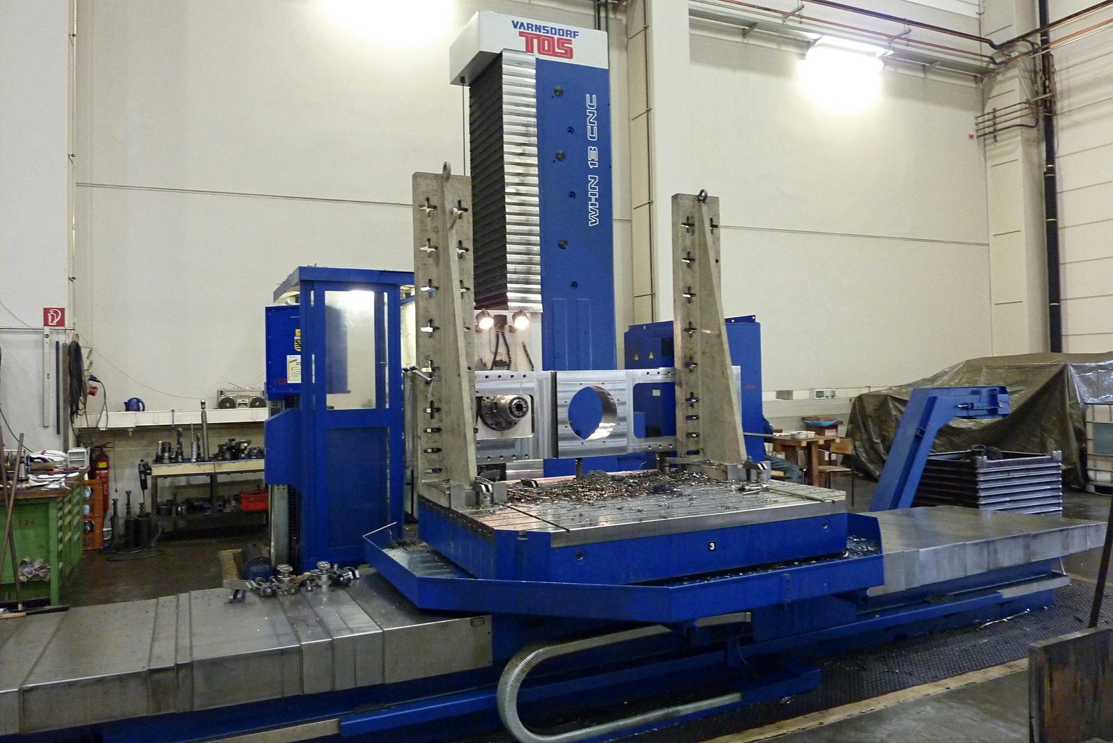
The name dates from a time when the machine mainly had one task: producing bores in large castings and weldments and enlarging them to size. Today "boring mill" is the short form for the horizontal boring and milling machine. It is a universal machine that, besides boring, also mills, faces and cuts threads. It differs from a horizontal machining centre mainly in two respects: in the workpiece size it is built for and, on many types, in the extendable boring spindle. With it, the tool reaches deep into the workpiece.
The feature that determines everything else is the horizontal spindle. It reaches the side faces of a workpiece, which is where bearing seats, flange holes and mating surfaces are located. With a rotary table, several sides are machined one after the other without re-clamping the workpiece. This produces the accuracy for which a boring mill is chosen: all dimensions from one setup refer to the same coordinate system.
In enquiries the term usually appears as a line in the routing sheet, as a note "boring mill work" on the drawing or as the question whether a component "has to go on the boring mill". This article explains three things: what the machine can do, which types exist and what decides whether a boring mill or another machine is the better choice.
Design: bed, column, headstock and rotary table
A boring mill consists of a few large assemblies. Their movements carry axis designations that recur in machine data and quotations:
- Machine bed and column: the bed carries the guideways. The column stands vertically on it and absorbs the machining forces. Its rigidity limits how much material a cut can remove.
- Headstock (Y axis): it travels up and down the column and determines the height at which boring takes place.
- Work spindle and boring spindle (W axis): the work spindle drives the tool. On many boring mills the boring spindle can also be extended out of the headstock. This lets the tool reach into deep bores without the table or column having to follow.
- Table (X and Z axes): it travels across and along the spindle and brings the workpiece into position.
- Rotary table (B axis): it rotates the workpiece about the vertical axis. This allows a machine whose spindle points in only one direction to reach all four side faces.
- Outboard support: with long boring bars, a bearing on the opposite side of the workpiece supports the bar. This produces aligned bores through the entire workpiece in a single pass.
The letters are not assigned in the same way by every manufacturer. When comparing machine data, what counts is therefore the direction – "cross", "vertical" or "longitudinal" – not just the letter.
Five operations a boring mill can perform
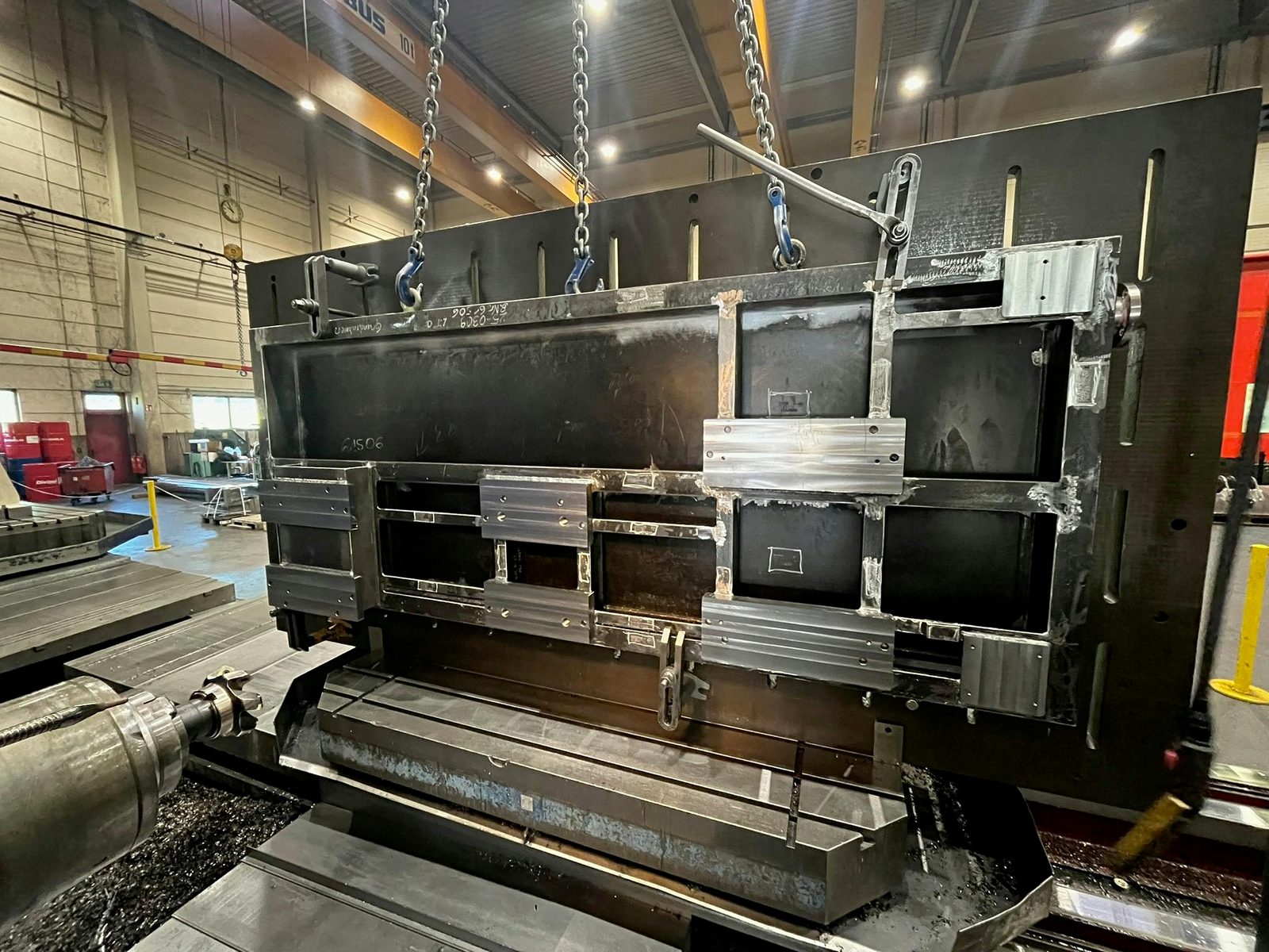
The strength of the machine lies in carrying out several operations on one workpiece without re-clamping:
- Drilling: through holes and blind holes, including deep ones and large diameters.
- Boring (precision boring): a single-point tool brings an existing bore to its final size. This produces fit bores with tight diameter tolerances and bearing seats that are precisely aligned. The boring mill was originally built for this operation.
- Milling: mating surfaces, slots and pockets, typically on the side faces.
- Facing: a radially adjustable tool faces the end surface around a bore flat and at right angles to the bore axis, for example as a seating face for a flange or bearing cover.
- Thread cutting: threads in connection holes, in the same reference system as the bore itself.
The advantage is the relationship between the features. Producing a bearing seat, mating surface and tapped holes in one setup keeps them in a common reference system and avoids the alignment errors that re-clamping can introduce.
Types: table-type boring mill and floor-type boring mill
Boring mills are distinguished by what moves: the workpiece or the machine.
On a table-type boring mill the workpiece sits on a table that travels across and along, usually with a rotary table. The column is fixed or travels in one direction only. This type offers multi-side machining via the rotary table. It is suitable for workpieces whose size and weight the table can take.
On a floor-type boring mill the workpiece stays still on a large clamping plate firmly anchored in the floor. Instead, the column with the headstock travels along the plate on a bed. Because no table has to carry and move the workpiece, this type is intended for the largest and heaviest parts. Between the two forms there are hybrid designs.
The travelling-column milling centre works on the same principle: the workpiece stands still, the machine moves. A travelling column with a swivelling milling head moves along the workpiece and mills, drills and bores. On long components, the travel therefore extends far beyond what a table could move.
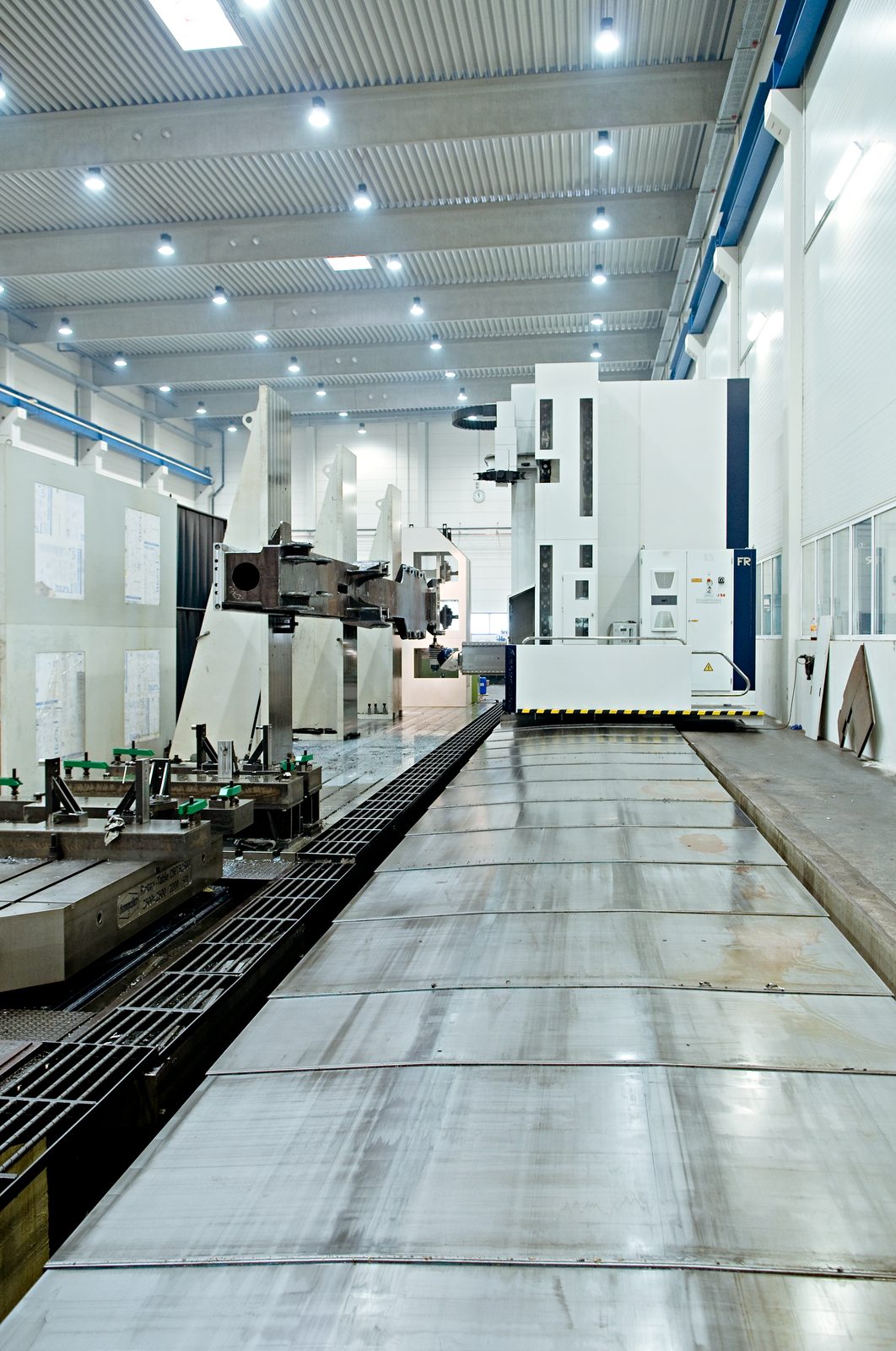
CNC travelling-column milling centre for long and tall components
Boring mill, travelling-column mill, gantry mill or radial drill?
Which machine machines a component follows from its geometry and from which dimensions have to be correct relative to each other. The short version:
| Machine | Principle | Strong at | Limit |
|---|---|---|---|
| Horizontal boring mill | Horizontal spindle, workpiece on cross table and rotary table | Bores and surfaces on several sides that have to be correct relative to each other: housings, bearing blocks, gearbox and machine columns | Workpiece size limited by table and travels; for long, flat parts a detour |
| Travelling-column milling centre | Column with swivelling milling head travels along the stationary workpiece | Long and tall components: frames, mast assemblies, machine beds | For compact parts with bores on all sides, the boring mill with rotary table is the more direct route |
| Gantry milling machine | Gantry spans the workpiece, the spindle works from above | Long, flat components with large flat surfaces and bore patterns on the top: base plates, cross members, frames | Side faces and bores transverse to the longitudinal axis only with an angle head or by re-clamping |
| Radial drilling machine | Drilling head on a swivelling arm on a column, the workpiece stands still | Many holes and threads on large parts whose position is adequately defined by marking out or a drilling template | No milling; tight positional tolerances between holes depend on marking out or a fixture |
| Vertical lathe | The workpiece rotates on a horizontal faceplate, the tool stands still | Rotationally symmetrical large parts: rings, flanges, hubs, bearing seats around one axis | Only for parts that can rotate about one axis; lateral bore patterns need a second machine |
The rule of thumb: if bores on several sides of a part have to be correct relative to each other, it is the boring mill. If the part is long and the machining is on top, it is the gantry milling machine. If the part is round, it is the vertical lathe. If there are many holes without a tight relationship to each other, it is the radial drilling machine.
When a boring mill is not the right machine
The best choice depends on the features to be machined and their relationship to one another. These tasks may be better suited to another machine:
- Long components machined on the top: a cross member several metres long with a bore pattern on the top would have to be repositioned several times on the boring mill. On the gantry milling machine, the bore pattern is produced in one setup.
- Simple hole patterns without a tight positional relationship: through holes for bolts whose position tolerates the accuracy of marking out or a template leave the boring mill's strength unused. The radial drilling machine handles them with less effort.
- Rotationally symmetrical parts: on a ring or a hub, the inner and outer diameters have to run true to each other. On the vertical lathe both are produced in one pass. On the boring mill the outer diameter can only be reached by circular milling or by re-clamping.
- Workpieces beyond table and travels: if the part projects beyond the table or the bores are further apart than the axes can reach, a travelling-column or gantry centre is the right machine. It leaves the part where it is and moves itself.
A boring mill is particularly useful when bearing seats, mating surfaces and features on several sides must share an accurate reference system. That relationship, rather than the presence of a bore alone, guides the choice.
What the drawing must specify for machine selection
The drawing does not have to name the machine. It has to contain the information from which the choice of machine follows: datum system and datum surfaces, position and orientation tolerances of the bores relative to each other (coaxiality, parallelism, perpendicularity), fits of the bearing seats, such as H7, and the required surface finishes.
A note such as “to be produced on a boring mill” fixes the route before the setup has been assessed. Specifying the required geometry and tolerances gives production planning room to choose the appropriate machine and sequence. The dimensional report then demonstrates whether the finished component meets the drawing.
Helpful, by contrast, is information that the drawing does not show: which surfaces carry load when installed, which bores will later be bolted to a mating part and whether the part will be welded after machining. Such information influences the sequence of operations more than any machine specification.
Choosing between the machines at Bock
In our production facility in Lorch there are three identical CNC horizontal boring mills TOS-Varnsdorf WHN 13. They have a boring spindle of Ø 130 mm and travels of 3,500 mm cross, 2,500 mm vertical and 1,200 mm longitudinal. Their 360° rotary table allows multi-side machining in one setup, controlled by a Heidenhain iTNC 530. Alongside them are the machines between which the choice described in this article is made:
- the travelling-column milling and boring centre Soraluce FR 20,000 with 20,000 mm × 4,000 mm × 1,600 mm travel
- two gantry milling machines Zayer Thera W with up to 26 m travel
- four machines for radial drilling and tapping: drilling up to Ø 90 mm, threads M2–M60, reach up to 3,000 mm
- three vertical lathes up to Ø 4,800 mm turning diameter
Which of them machines a component is decided by us on the basis of the drawing. If a part has to pass through several machines, for example the bore pattern on the top on the gantry mill and the bearing seats on the end faces on the boring mill, it stays in-house. Welding, sandblasting and painting follow in the same company. We do not operate a floor-type boring mill: workpieces that exceed the boring mill tables are machined by the travelling column and gantry mills, on the principle of leaving the part where it is and moving the machine.
Frequently asked questions about the boring mill
What is a boring mill?
A boring mill, in full a horizontal boring and milling machine, is a machine tool with a horizontal work spindle. It drills, bores, mills, faces and cuts threads on large workpieces. Usually it machines several sides in one setup via a rotary table. It is chosen when bores and surfaces on different sides of a part have to be positioned precisely relative to each other. At Bock such parts run on three CNC boring mills TOS-Varnsdorf WHN 13.
What is the difference between a boring mill and a radial drilling machine?
On the boring mill, bore, surface and thread come from one CNC setup and therefore relate to each other in a common reference system. On the radial drilling machine the workpiece stands still, and the drilling head is brought to the drilling position via a swivelling arm. The position of the holes there results from marking out or a fixture. The radial drilling machine is the choice for many holes without a tight positional relationship, the boring mill for bearing seats and fit bores that have to be correct relative to each other. Bock has both in-house and allocates the part.
What is the difference between a table-type boring mill and a floor-type boring mill?
On the table-type boring mill a cross table and rotary table move the workpiece. On the floor-type boring mill the workpiece stands on a fixed clamping plate, and the column travels along it. The table-type boring mill offers multi-side machining via the rotary table. The floor-type boring mill is intended for parts that no table can carry any more. At Bock this role for large parts is taken on by the travelling-column milling centre and the gantry mills, which likewise move along the stationary workpiece.
What does boring (Ausspindeln) mean?
Boring (also called precision boring) means bringing an existing bore to its final size with a single-point tool. This produces fit bores and bearing seats with tight diameter tolerances that are precisely aligned. On the boring mill this is done in the same reference system as the other bores and surfaces of the part. That is why boring is the typical reason for putting a part on the boring mill.
Boring mill or gantry mill – which machine suits my component?
That depends on where the machining is. If bores and surfaces are on several sides and have to be correct relative to each other, the boring mill with rotary table is the right fit. If the component is long and the machining is mainly on the top, as with base plates and cross members, the gantry mill is the right fit. At Bock both are in the same plant. We take care of the allocation on the basis of your drawing.
Do I have to specify which machine my component is to be produced on?
No. The drawing specifies the result: datum system, positional tolerances, fits and surface finishes. Which machine, which sequence and how many setups are needed is decided by us. Helpful are notes that are not on the drawing, for example which surfaces carry load when installed or whether the part will be welded after machining.
Which boring mills does Bock use?
Three identical CNC horizontal boring mills TOS-Varnsdorf WHN 13 with boring spindle Ø 130 mm, travels of 3,500 mm × 2,500 mm × 1,200 mm, 360° rotary table and Heidenhain iTNC 530 control. For larger parts there are also the travelling-column milling centre Soraluce FR 20,000 and two gantry milling machines Zayer Thera W.
Standards
Standards are cited by number and edition; their text is subject to a charge and is therefore not linked.
- Positional tolerances of the bores relative to each other (coaxiality, parallelism, perpendicularity) and how they are specified on the drawing DIN EN ISO 1101 – Geometrical product specifications (GPS) – Geometrical tolerancing – Tolerances of form, orientation, location and run-out
- Fits of the bearing seats, such as H7 DIN EN ISO 286-1 – Geometrical product specifications (GPS) – ISO code system for tolerances on linear sizes – Part 1: Basis of tolerances, deviations and fits